
Sensor mounting structure for vehicle

a technology for sensors and mounting structures, applied in bumpers, using reradiation, instruments, etc., can solve the problems of water drainage from the cowl, and the peripheral information detection sensors may be exposed to water, so as to achieve the effect of suppressing water more effectively

Active Publication Date: 2020-05-21
TOYOTA JIDOSHA KK
View PDF0 Cites 9 Cited by
  • Summary
  • Abstract
  • Description
  • Claims
  • Application Information

AI Technical Summary

Benefits of technology

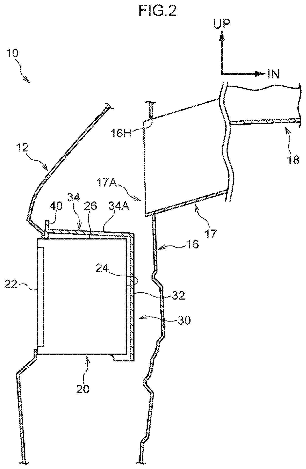
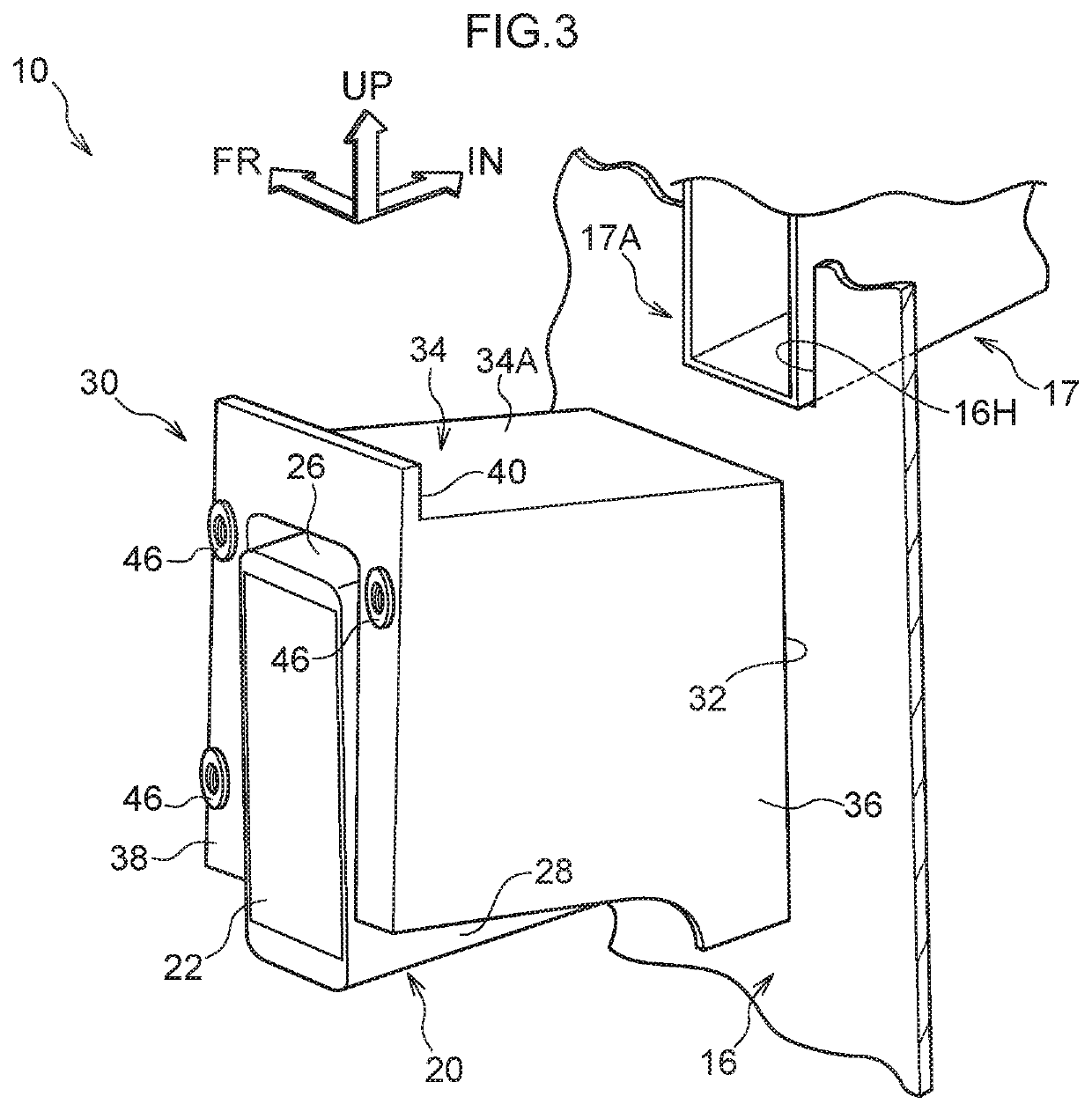
The present disclosure provides a sensor mounting structure for a vehicle that can prevent a peripheral information detection sensor from being exposed to water due to drainage from a cowl. This is achieved by designing a mounting bracket with an upper wall that extends towards the vehicle's outer side and covers at least a portion of the top surface of the sensor. The upper wall is inclined towards the vehicle's upper side to facilitate the flow of water along its surface towards the vehicle's inner side, reducing the accumulation of water on the top surface of the bracket and the exposure of the sensor's detection portion to water. Additionally, a rib on the mounting bracket further suppresses water from reaching the sensor. This results in the effective prevention of water exposure to the sensor, improving its performance and longevity.

Problems solved by technology

In the above-described techniques, because the peripheral information detection sensors are disposed relatively close to a cowl, there is the concern that, depending on drainage paths of the cowl, the peripheral information detection sensors may be exposed to water due to drainage from the cowl.

Method used


Image

  • Sensor mounting structure for vehicle
  • Sensor mounting structure for vehicle
  • Sensor mounting structure for vehicle

Examples


embodiment

Structure of Embodiment

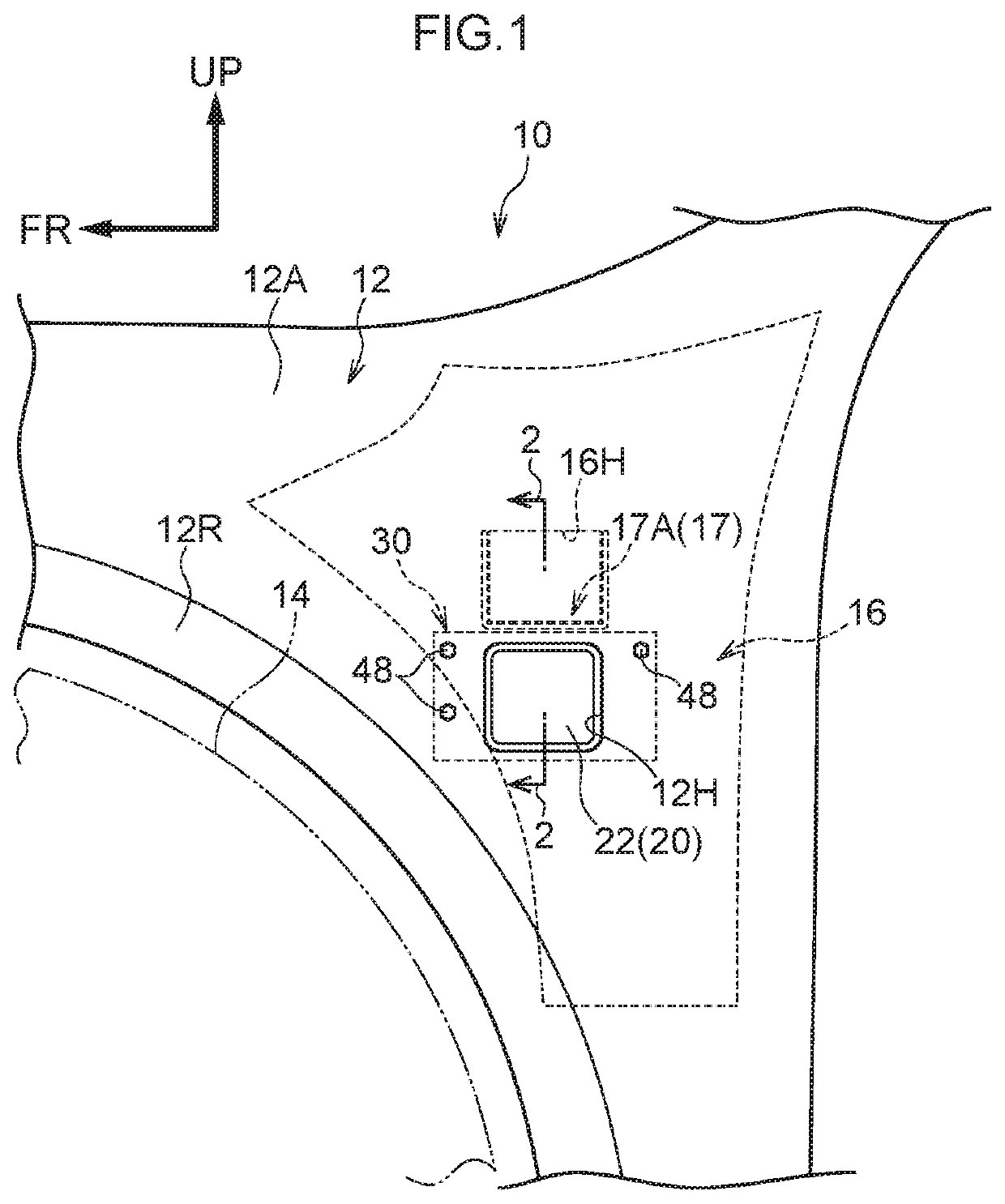
[0020]A sensor mounting structure for a vehicle relating to the present embodiment is shown in FIG. 1 in a simplified side view and in a state of being seen from a vehicle transverse direction outer side. Fender panel (also called “front panel”) 12 is disposed at a vehicle front side of an unillustrated front side door. The fender panel 12 has an outer side wall portion 12A that structures a side surface, i.e., a design surface, of a vehicle front portion 10. The outer side wall portion 12A is disposed at a vehicle upper side of a front wheel 14. A wheel arch portion 12R is formed at the outer side wall portion 12A along an upper side of an outer periphery of the front wheel 14. Further, an opening portion 12H, which is for a portion of a peripheral information detection sensor 20 to face toward a lateral side of the vehicle, is formed so as to pass-through a rear portion in the vehicle longitudinal direction of the outer side wall portion 12A. The fender pane...


PUM


Abstract

A sensor mounting structure for a vehicle includes: a fender panel; a cowl side panel provided at a lateral side of a cowl and disposed at an inner side, in a vehicle transverse direction, of the fender panel; a peripheral information detection sensor disposed at an inner side of the rear portion of the fender panel and at an outer side of the cowl side panel, the peripheral information detection sensor having a detection portion facing toward an outer side; and a mounting bracket having a vertical wall to which the peripheral information detection sensor is fixed, the mounting bracket being fixed to a vehicle body side member and being disposed between the peripheral information detection sensor and the cowl side panel.

Description

CROSS-REFERENCE TO RELATED APPLICATION[0001]This application claims priority under 35 USC 119 from Japanese Patent Application No. 2018-217713 filed Nov. 20, 2018, the disclosure of which is incorporated by reference herein in its entirety.BACKGROUNDTechnical Field[0002]The present disclosure relates to a sensor mounting structure for a vehicle.Related Art[0003]Vehicles having a device for detecting information at the periphery of the own vehicle are known (see, for example, Japanese Patent Application Laid-Open (JP-A) No. 2017-193223 and JP-A No. 2018-134936). For example, JP-A No. 2017-193223 discloses a structure in which peripheral information detection sensors are disposed at inner sides of fender panels at a vehicle front portion. To briefly describe this structure, the peripheral information detection sensors have detection portions, which detect peripheral information regarding the vehicle, and are disposed such that the detection portions face toward vehicle outer sides.SUM...

Claims


Application Information

Patent Timeline
Patent Type & Authority Applications(United States)
IPC IPC(8): B60R19/48
CPCB60R2019/247G01S2015/938G01S2013/93275G01S15/931B60R19/483G01S13/931G01S17/931B62D25/16B62D25/081G01S7/521G01S7/4813G01S7/027
Inventor KATAOKA, YUSUKEIWAMATSU, RYOSHIBATA, KENSAKU
Owner TOYOTA JIDOSHA KK
Learn More