
Cutting head of a grass trimmer

a cutting head and grass trimmer technology, applied in the field of cutting heads of grass trimmers, can solve the problems of increasing the output power of the motor, affecting the performance of the motor, and affecting the service life of the battery, so as to prolong the service life of the cutting head, avoid the increase of load, and slow down the wear speed of the supporting cap

Inactive Publication Date: 2020-05-21
CHERVON HK LTD WANCHAI
View PDF0 Cites 1 Cited by
  • Summary
  • Abstract
  • Description
  • Claims
  • Application Information

AI Technical Summary

Benefits of technology

The described cutting head structure has several benefits. It reduces wear and tear on the cutting head, saves power, and improves user comfort. The cutting head is designed to freely rotatable, which prevents it from hitting the ground or dragging during operation. This reduces the load on the cutting head and slows down the wear speed of the supporting cap, which leads to a longer service life for the cutting head. This also reduces the output power consumption of the motor, extends the life of the battery, and makes the user feel more comfortable.

Problems solved by technology

Since the bumping head contacts the ground, it is subjected to wear from the ground during rotation, and furthermore, output power of the motor is increased and service life of the battery is affected.
Regarding cutting heads with automatic line feed and manual line feed, an operator unconsciously causes the cutting head to contact the ground frequently during practical use, which inevitably accelerates wear of the cutting head which is rotating at a high speed, increases the power consumption of the grass trimmer and affects the performance of the motor.
Although instructions to avoid contacting the bumping cap with the ground are provided in the specification of many grass trimmer products, this still cannot fundamentally solve the above issues.

Method used


Image

  • Cutting head of a grass trimmer
  • Cutting head of a grass trimmer
  • Cutting head of a grass trimmer

Examples


Embodiment Construction

[0025]The following description of example methods and apparatus is not intended to limit the scope of the description to the precise form or forms detailed herein. Instead the following description is intended to be illustrative so that others may follow its teachings.

[0026]The subject cutting head will now be described in detail with reference to figures.

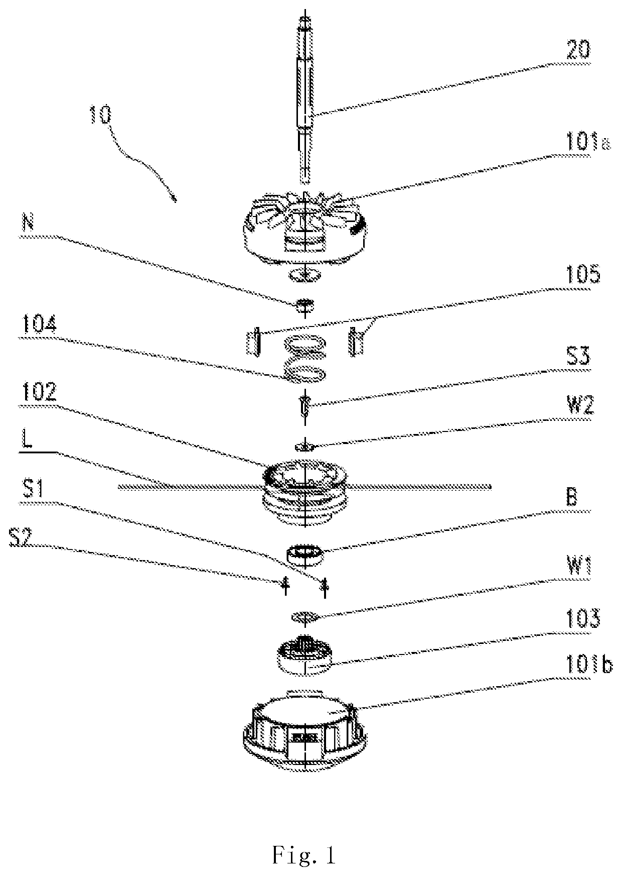
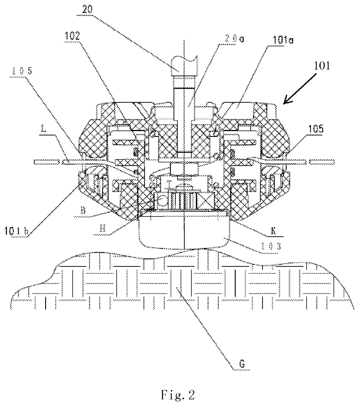
[0027]FIG. 1 is an exploded view of an exemplary cutting head. FIG. 2 is a partial cross-sectional view of the cutting head of FIG. 1 after being duly assembled. Referring to FIG. 1 and FIG. 2, parts except for a motor shaft and a tapping cap are shown in the cross-sectional view, and a cutting head 10 is connected to a motor output shaft 20 of a grass trimmer.

[0028]The cutting head 10 includes a housing 101, a line spool 102, a supporting cap 103 and a compression spring 104. In the present embodiment, the housing 101 includes an upper cover 101a and a lower cover 101b which are fixed by snap fitting. The upper cover 101a is moun...


PUM


Abstract

A cutting head for use with a cutting tool, such as a grass trimmer. The cutting head has a housing, a line spool and a supporting cap. One end of the housing is coupled to an end of a motor output shaft and another end has an opening. A line spool is disposed in the housing and rotates along with the housing. At least one end of a line wound around the line spool extends out of the housing. The supporting cap is rotatably disposed at the end of the line spool adjacent to the opening and is exposed to an exterior of the housing through the opening.

Description

CROSS REFERENCE TO RELATED APPLICATION[0001]This application is a continuation of U.S. patent application Ser. No. 15 / 407,838 filed Jan. 17, 2017, which is a divisional of U.S. Ser. No. 14 / 295,634, filed Jun. 4, 2014 now abandoned, which claims the benefit of CN 201310229816.7, filed on Jun. 9, 2013, and CN 201310283731.7, filed on Jul. 5, 2013, the disclosures of which are each incorporated herein by reference in their entirety.FIELD OF THE DISCLOSURE[0002]The present disclosure relates to the field of gardening power tools and, more particularly, to a cutting head of a grass trimmer.BACKGROUND OF RELATED ART[0003]A grass trimmer is a universal and practical gardening tool, and is particularly adapted to trim grass at a location such as a villa lawn and a garden lawn. Grass trimmers currently available in the market are roughly classified into the following types: bump line feed, automatic line feed, and manual line feed. When a grass trimmer feeds line by bumping, a user needs to ...

Claims


Application Information

Patent Timeline
IPC IPC(8): A01D34/416A01G20/12
CPCA01D34/4163A01G3/06A01D34/4162A01D34/416A01D34/4165
Inventor YAMAOKA, TOSHINARILI, HANZHENG
Owner CHERVON HK LTD WANCHAI
Learn More