
Heat pump system for vehicle

a heat pump and vehicle technology, applied in vehicle heating/cooling devices, vehicle/fuel cell control arrangement, transportation and packaging, etc., can solve the problems of complex system, large size and weight of cooling modules disposed in the front of the vehicle, and increase the size and weight of cooling modules, so as to achieve efficient heating and cooling, simplify the system of the heat pump system, and optimize the effect of performan

Active Publication Date: 2020-04-23
HYUNDAI MOTOR CO LTD +1
View PDF50 Cites 14 Cited by
  • Summary
  • Abstract
  • Description
  • Claims
  • Application Information

AI Technical Summary

Benefits of technology

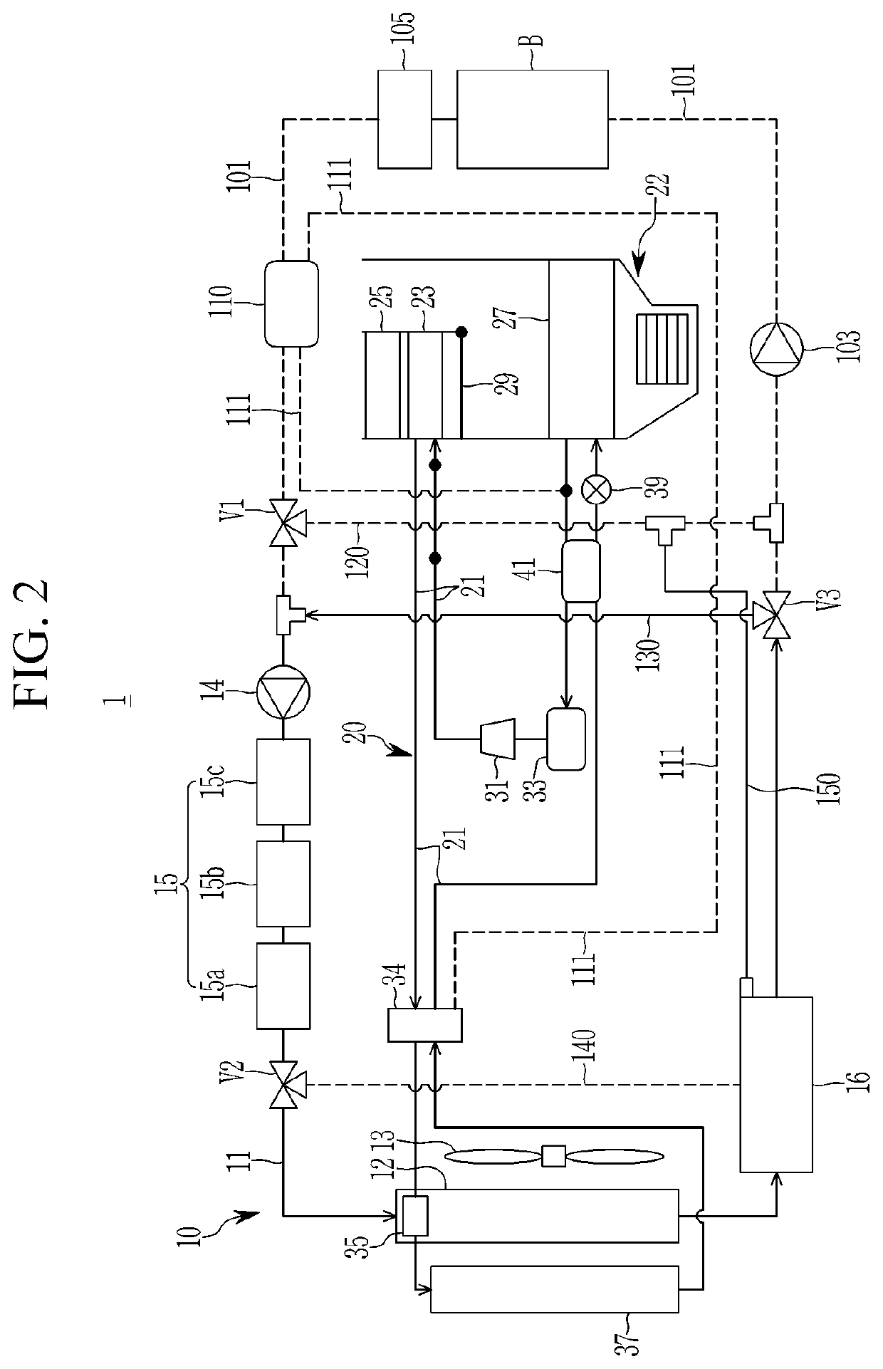
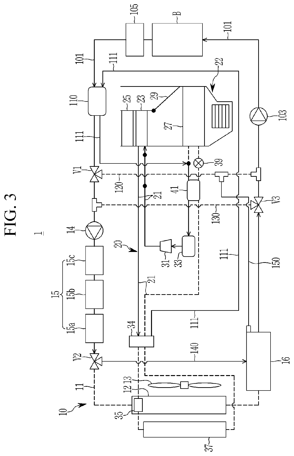
The present invention is a heat pump system for a vehicle that can cool the battery module using a single chiller that exchanges coolant and refrigerant. It includes an integrated control valve to adjust the flow of the refrigerant, reducing the number of valves. The system also has another chiller that recovers waste heat from the battery module, improving heating efficiency. The system simplifies the system, reduces manufacturing costs and weights, and improves space utilization. Overall, it helps manage the battery module for optimal performance and increases the vehicle's total mileage.

Problems solved by technology

Thus, the size and weight of a cooling module disposed in the front of the vehicle are increased, and a layout of connecting pipes for supplying a refrigerant or coolant to the heat pump system, the cooling part, and the battery cooling system inside an engine compartment becomes complex.
In addition, since the battery cooling system that heats or cools the battery is provided separately based on a state of the vehicle and thus, the battery may operate in an optimal state, a plurality of valves that connect the respective connecting pipes are applied, thus noise and vibration are transmitted to the interior of the vehicle, resulting in poor ride comfort.

Method used


Image

  • Heat pump system for vehicle
  • Heat pump system for vehicle
  • Heat pump system for vehicle

Examples


Embodiment Construction

[0057]It is understood that the term “vehicle” or “vehicular” or other similar term as used herein is inclusive of motor vehicles in general such as passenger automobiles including sports utility vehicles (SUV), buses, trucks, various commercial vehicles, watercraft including a variety of boats and ships, aircraft, and the like, and includes hybrid vehicles, electric vehicles, plug-in hybrid electric vehicles, hydrogen-powered vehicles and other alternative fuel vehicles (e.g. fuels derived from resources other than petroleum). As referred to herein, a hybrid vehicle is a vehicle that has two or more sources of power, for example both gasoline-powered and electric-powered vehicles.

[0058]Although exemplary embodiment is described as using a plurality of units to perform the exemplary process, it is understood that the exemplary processes may also be performed by one or plurality of modules. Additionally, it is understood that the term controller / control unit refers to a hardware devi...


PUM


Abstract

A vehicle heat pump system is provided. The system includes a battery coolant line connected to a battery module and into which a coolant flows. A cooling device includes a radiator and a first water pump connected to a coolant line, to circulate a coolant in the coolant line to cool electrical equipment, and to be selectively connected to the battery coolant line via a first valve. A chiller is disposed in the battery coolant line, to be connected to a refrigerant line of an air conditioner via a connecting line, and to adjust a temperature of a coolant or a refrigerant by selectively exchanging heat between the coolant and refrigerant flowing into the chiller. An integrated control valve is connected to the refrigerant line and the connecting line to adjust a refrigerant flow direction and to selectively expand a refrigerant passing through the inside of the integrated control valve.

Description

CROSS-REFERENCE TO RELATED APPLICATION[0001]This application claims priority to and the benefit of Korean Patent Application No. 10-2018-0126604 filed on Oct. 23, 2018, the entire contents of which are incorporated herein by reference.BACKGROUND(a) Field of the Invention[0002]The present invention relates to a heat pump system for a vehicle, and more particularly, to a heat pump system for a vehicle that cools a battery module and improves heating efficiency by recovering waste heat of electrical equipment and the battery module, by using a single chiller in which a refrigerant and a coolant are heat-exchanged.(b) Description of the Related Art[0003]Generally, an air conditioner for a vehicle includes an air conditioner system that circulates a refrigerant to heat or cool an interior of the vehicle. The air conditioner system, which maintains a fresh indoor condition by maintaining an indoor temperature of a vehicle at an appropriate temperature regardless of an outdoor temperature ...

Claims


Application Information

Patent Timeline
Patent Type & Authority Applications(United States)
IPC IPC(8): B60H1/00B60H1/14B60H1/06B60H1/32B60H3/02
CPCB60H1/323B60H2001/3255B60H1/00921B60H2001/003B60H1/00885B60H1/143B60H1/00485B60H1/00278B60H1/06B60H1/00342B60H1/00385B60H3/02B60H2001/3291B60H2001/3267B60H1/00328B60H1/00321B60H1/22B60H1/3204B60L58/26B60H2001/2268B60H2001/00307B60H2001/00949B60H2001/00928Y02T10/70B60H1/32284
Inventor LEE, KILWOOOH, DONG SEOK
Owner HYUNDAI MOTOR CO LTD
Learn More