Device For Reducing Or Even Eliminating Tonal Noise For An Aircraft Powerplant De-Icing System

Inactive Publication Date: 2020-04-02
AIRBUS OPERATIONS (SAS)
View PDF0 Cites 0 Cited by
  • Summary
  • Abstract
  • Description
  • Claims
  • Application Information

AI Technical Summary

Benefits of technology

The invention aims to reduce or even eliminate noise generated by the D-duct during the NAI system's inactivity. This is achieved by installing deflectors at the edge of each orifice to redirect the vortices outside the cavity while preventing deformation. As a result, tonal noise and loss of hot air flow rate are minimized, improving the efficiency of the de-icing system.

Problems solved by technology

Thus, the retroactive loop between the two edges of the orifice can only be established with difficulty to produce a tonal noise capable of exciting a cavity mode of the D-duct when the NAI system is inactive.
In addition, the cavity of the D-duct will not be able to resonate or at least will resonate with a greatly reduced sound level.

Method used


Image

  • Device For Reducing Or Even Eliminating Tonal Noise For An Aircraft Powerplant De-Icing System
  • Device For Reducing Or Even Eliminating Tonal Noise For An Aircraft Powerplant De-Icing System
  • Device For Reducing Or Even Eliminating Tonal Noise For An Aircraft Powerplant De-Icing System

Examples


Embodiment Construction

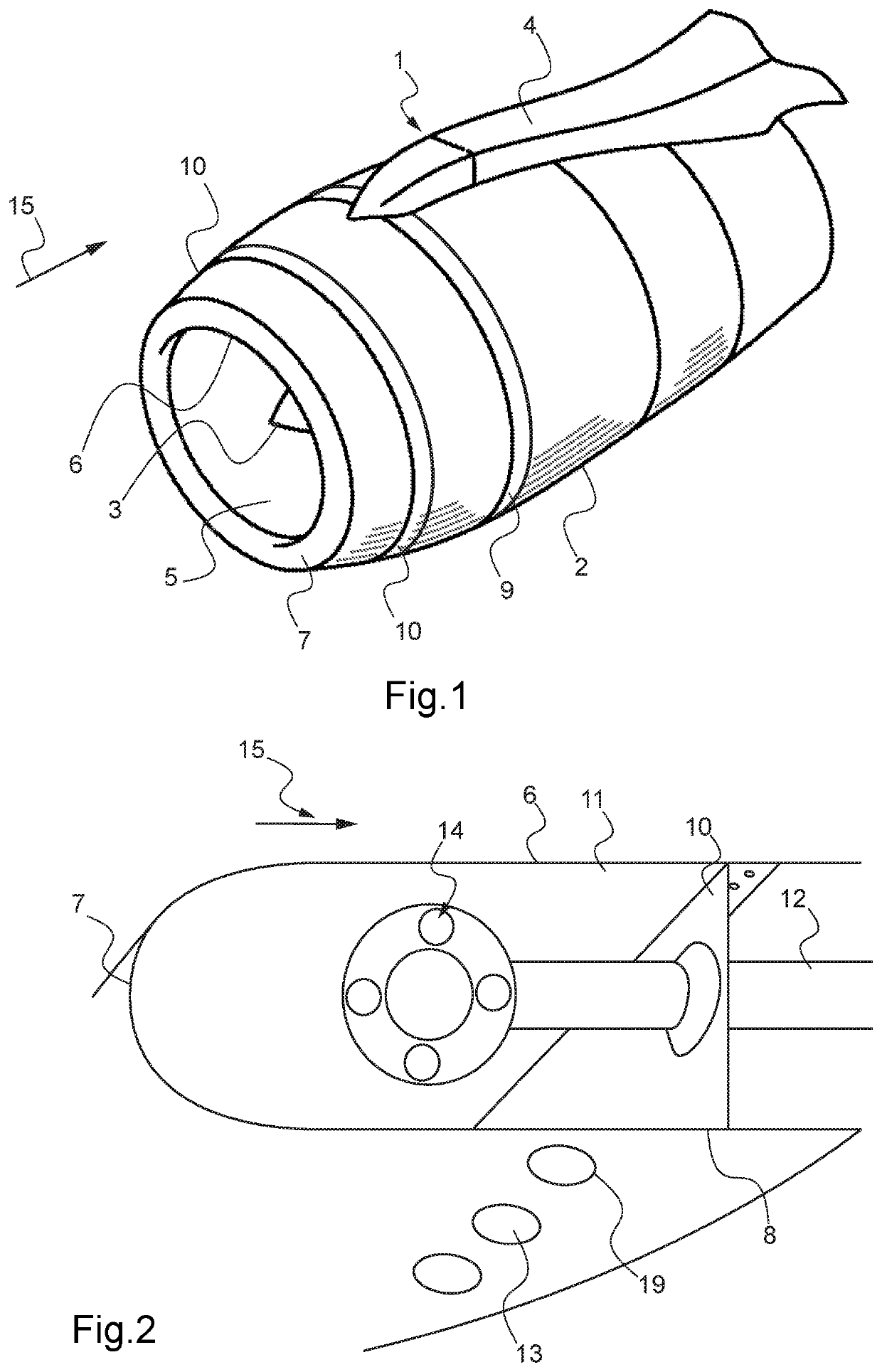
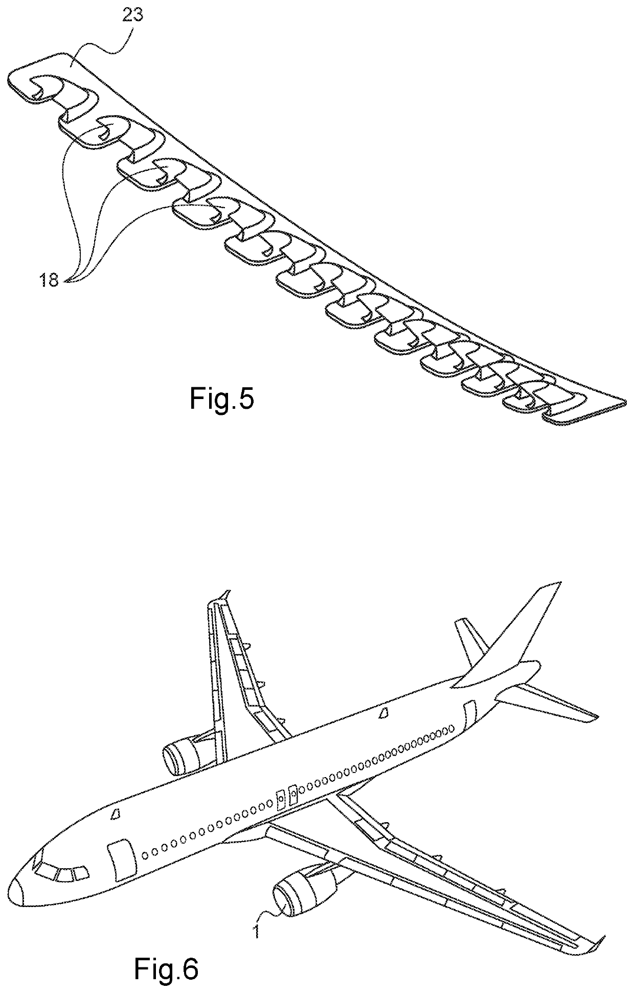
[0030]FIG. 1 shows an aircraft powerplant of the turboprop type. The relative axial positions of the components of the powerplant 1 and the different systems and devices described will hereafter be given relative to the general direction 15 of the air flowing through the powerplant 1 and along the outer surfaces thereof.

[0031]This type of powerplant for commercial aircraft typically includes a nacelle 2 in which an engine 3 is located. The nacelle 2 is generally suspended underneath the wing or fixed on a rear fuselage portion by a support strut 4.

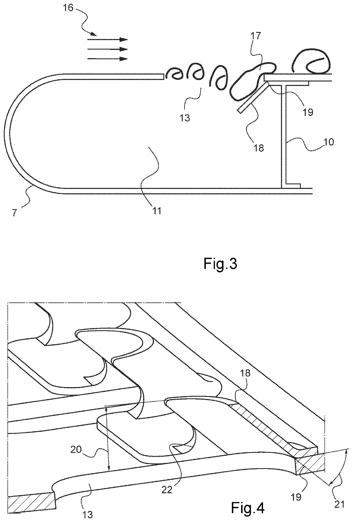
[0032]On the front portion of the nacelle 2 is an air intake 6 that opens into an inner duct 5 formed by an inner wall of the nacelle surrounding the engine 3. The inner duct 5 channels the air towards the engine 3. The air intake 6 is provided with a lip 7, the inner edge of which meets the inner duct 6 and the outer edge of which meets an outer wall 8 of the nacelle. This lip 7 has an aerodynamic function that consists of capturing the a...


PUM


Abstract

A device for an aircraft powerplant de-icing system making it possible to reduce or eliminate a tonal noise generated by a flow of air along a surface having an orifice opening into a cavity extending on the side opposite this surface, the orifice having a downstream edge relative to the direction of flow of the air, includes a deflector positioned next to the downstream edge, extending towards the inside of the cavity, and oriented perpendicularly to the direction of flow of the air to divert towards the outside of the orifice vortices formed in the shear layer due to the flow of the air along the surface over each orifice. The deflector at the downstream edge of each exhaust orifice of the de-icing system makes it possible to redirect the vortices outside the cavity while preventing them from being greatly deformed when they pass over the downstream edge.

Description

FIELD OF THE INVENTION[0001]The invention relates to aircraft powerplants and more particularly to a de-icing system installed in the lip of a powerplant nacelle.BACKGROUND OF THE INVENTION[0002]Commercial aircraft have powerplants that are usually suspended underneath the wing or fixed on a rear fuselage portion. These powerplants generally have an engine located inside a nacelle fixed to the aircraft wing or fuselage by a support strut one end of which is connected to the outer wall of the nacelle and the other end of which is connected to the wing or fuselage. The axial positions of the different components of the powerplant are hereafter given relative to the direction of the air flow passing through it.[0003]On the front portion of the nacelle is an air intake that opens into an inner duct formed by an inner wall of the nacelle. The inner duct channels the air towards the engine, which can be a turboprop, for example. The air intake is provided with a lip, the inner edge of whi...

Claims


Application Information

Patent Timeline
IPC IPC(8): B64D33/02B64D15/04
CPCB64D33/02B64D2033/0233B64D15/04B64D2033/0206B64C2230/14B64C21/02B64C2230/08B64C2230/24B64D2033/0226F02C7/045F02C7/047F05D2250/314F05D2240/40Y02T50/10
Inventor FARGIER, THIERRYLE-FLEM, FRANCK
Owner AIRBUS OPERATIONS (SAS)
Why Eureka
Try Eureka