Flow cell and gas analyzing device having the same

a flow cell and gas analyzing technology, applied in the direction of instruments, heat measurement, temperature measurement of flowing materials, etc., can solve the problem of hard to handle the thermocouple in terms of strength, and achieve the effect of reducing strength, small heat capacity, and improving responsiveness

Inactive Publication Date: 2020-03-19
SHIMADZU CORP
View PDF1 Cites 0 Cited by
  • Summary
  • Abstract
  • Description
  • Claims
  • Application Information

AI Technical Summary

Benefits of technology

The present invention provides a flow cell that can suppress strength reduction and carry out a measurement with high responsiveness. This is achieved by integrating a thermocouple with the main body of the flow cell, which reduces the heat capacity and allows for the direct detection of the temperature of the sample gas before the heat is drawn by the main body. This results in a more precise measurement. Additionally, the joint part of the metal wires constructing the thermocouple is positioned in proximity to the opening portions of the flow cell, allowing for direct contact with the sample gas, regardless of the installation angle or gas distributing direction. Overall, this invention improves the accuracy and responsiveness of flow cell measurements.

Problems solved by technology

Therefore, there is a problem that it is hard to handle the thermocouple in terms of strength.

Method used


Image

  • Flow cell and gas analyzing device having the same
  • Flow cell and gas analyzing device having the same
  • Flow cell and gas analyzing device having the same

Examples


first embodiment

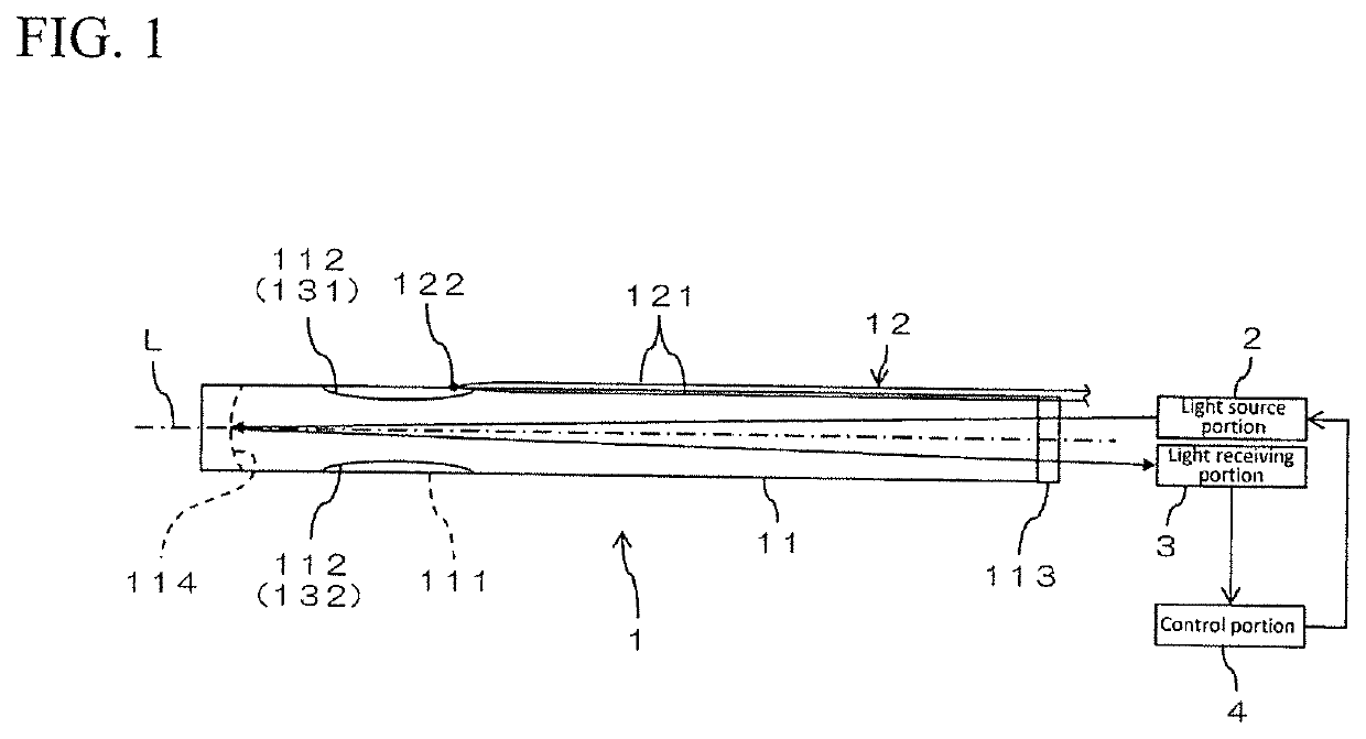
[0027]FIG. 1 is a schematic side elevational view showing an exemplary construction of a gas analyzing device according to a first embodiment of the present invention. The gas analyzing device according to the present embodiment is provided with a flow cell 1, a light source portion 2, a light receiving portion 3 and a control portion 4, and can measure concentration or partial pressure of a component to be measured in the sample gas, for example, using the TDLAS. The gas analyzing device can be applied, for example, to measurement of intake gas or exhaust gas of a motor vehicle, gas in a gas flue, gas generated in a plant facility, and gas in vacuum.

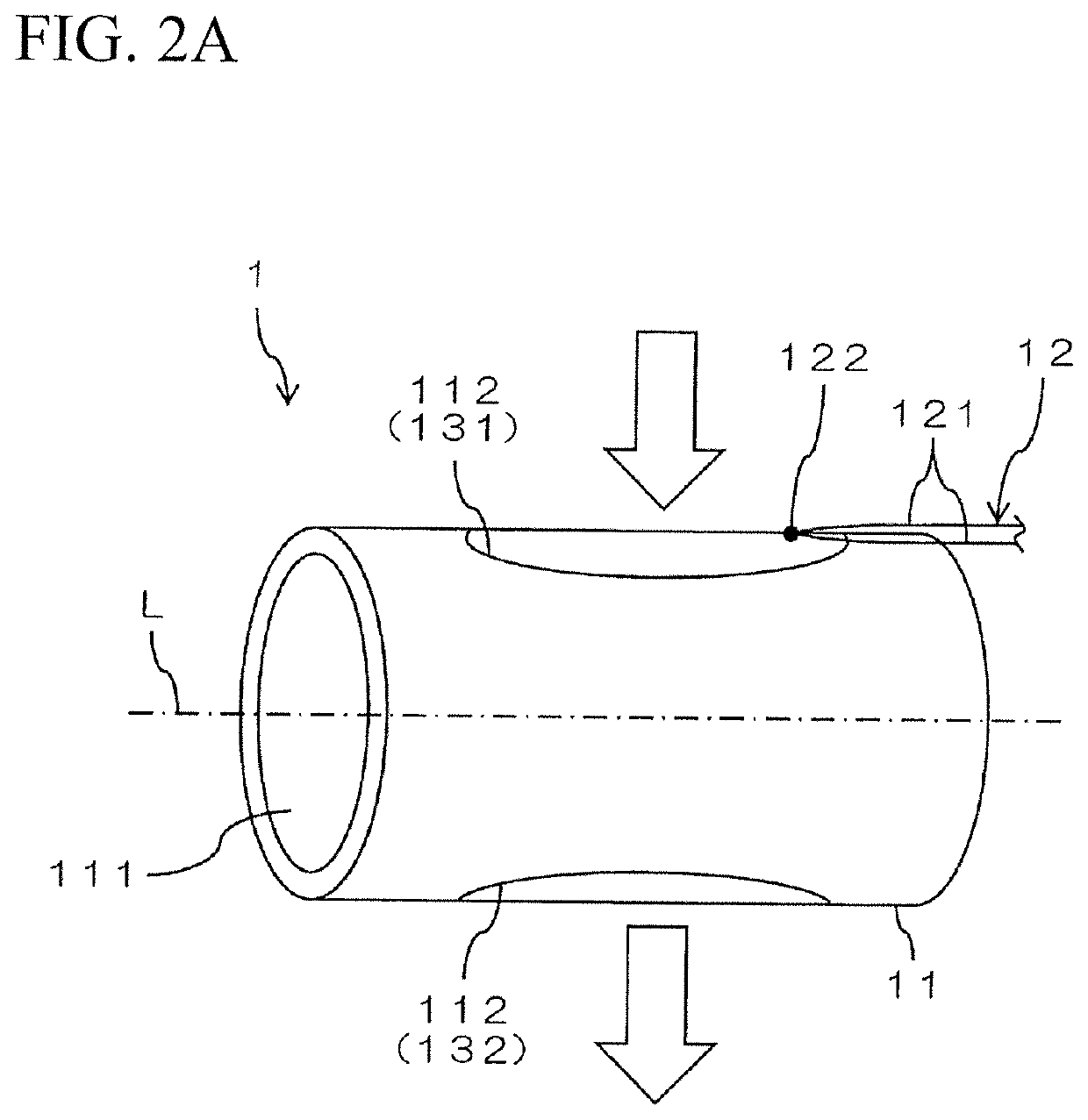
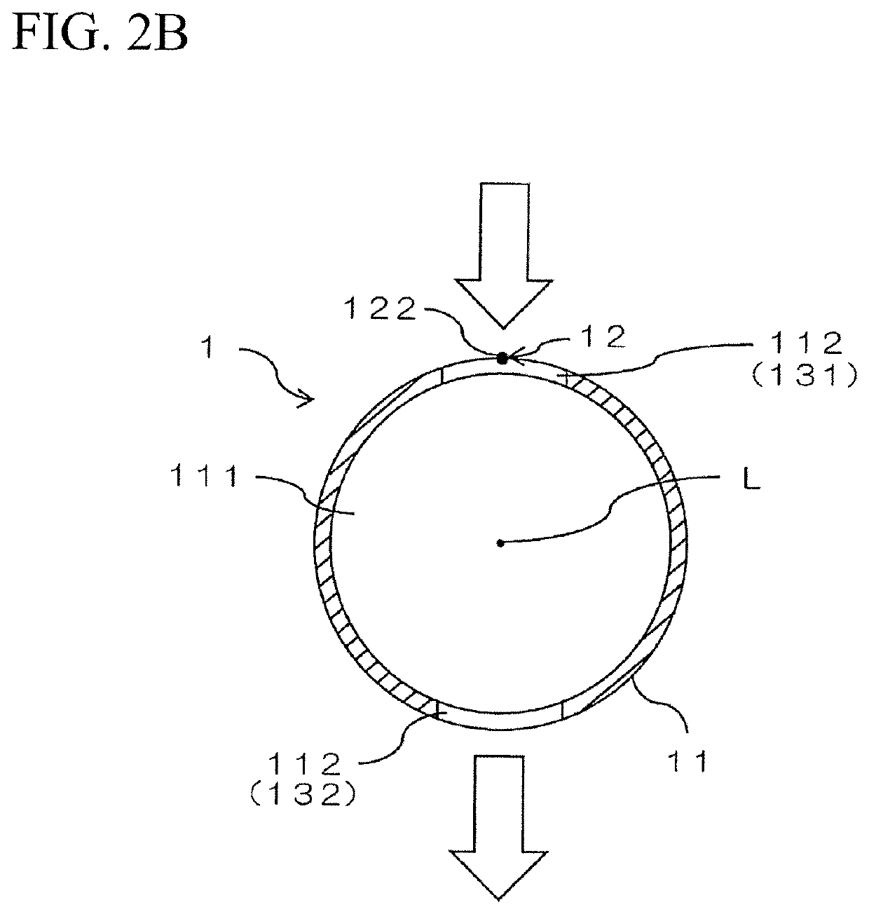
[0028]The flow cell 1 is provided with a tubular main body 11, and one thermocouple 12. In this example, the main body 11 is formed into a circular tube shape. The thermocouple 12 is integrally attached to the main body 11 by being directly fixed to a peripheral wall of the circular tubular main body 11.

[0029]The main body 11 extends in...

second embodiment

[0054]FIG. 4 is a schematic side elevational view showing an exemplary construction of a gas analyzing device according to a second embodiment of the present invention. The gas analyzing device according to the present embodiment is provided with a flow cell 1, a light source portion 2, a light receiving portion 3 and a control portion 4 in the same manner as the first embodiment, and can measure the concentration or the partial pressure of the component to be measured in the sample gas, for example, by using the TDLAS. Since the structures of the light source portion 2, the light receiving portion 3 and the control portion 4 are the same as those of the first embodiment, an illustration of these structures is omitted in FIG. 4.

[0055]The flow cell 1 is provided with a tubular main body 11, and a plurality of thermocouples 12. In this example, the main body 11 is formed into a circular tube shape. The plurality of thermocouples 12 is integrally attached to the main body 11 by being d...


PUM


Abstract

A flow cell has a tubular main body and a thermocouple. An internal space is formed in the main body, a plurality of opening portions allowing the internal space to communicate with an external portion is formed in a peripheral wall, and sample gas flowing from at least one of the plurality of opening portions passes through the internal space and flows out of the other opening portion. The thermocouple includes two metal wires which are integrally attached to the main body, and a joint part of the two metal wires is provided in the vicinity (proximate) of the opening portion closer to an upstream side of the sample gas in a distributing direction than a center axis line of the main body.

Description

CROSS REFERENCE TO RELATED APPLICATIONS[0001]This application relates to, but does not claim priority from, JP Ser. No.: JP2016-052493 filed Mar. 16, 2016 and published as JP Pub. No.: JP 2017-166978 on Sep. 21, 2017, the entire contents of which are incorporated herein fully by reference.BACKGROUND OF THE INVENTIONField of the Invention[0002]The present invention relates to a flow cell in which sample gas passes through an internal space formed within a tubular main body, and a gas analyzing device having the flow cell.Description of the Related Art[0003]As one of methods for measuring a concentration or a partial pressure of a component to be measured in sample gas, an absorption spectroscopy has been known. In the absorption spectroscopy, the sample gas is supplied into the measuring cell and light is irradiated into the measuring cell, so that the concentration or the partial pressure of the component to be measured is measured on the basis of spectrum obtained by a spectral ope...

Claims


Application Information

Patent Timeline
IPC IPC(8): G01N33/00G01N21/39
CPCG01N2021/399G01N21/39H01M8/18G01N33/0031G01K7/02G01K13/02G01N21/05G01N2201/1211G01N2201/1218G01K13/024Y02E60/50
Inventor OTERA, FUMIAKI
Owner SHIMADZU CORP
Why Eureka
Try Eureka