System and method for representing and displaying color accuracy in pattern matching by a vision system

a vision system and color accuracy technology, applied in the field of machine vision systems, can solve problems such as difficulty in a vision system, lack of high-contrast edges, and inability to accurately match trained and runtime color images

Active Publication Date: 2020-03-05
COGNEX CORP
View PDF7 Cites 1 Cited by
  • Summary
  • Abstract
  • Description
  • Claims
  • Application Information

AI Technical Summary

Benefits of technology

The patent identifies a mismatch that helps confirm the training model's accuracy and suggests parameters that may need adjustment. This helps identify defects in real-time objects and improves the overall quality of the model.

Problems solved by technology

It is challenging for a vision system to match certain imaged features to trained patterns.
This can result from a lack of high-contrast edges (which most pattern matching tools use to base matching decisions).
Nevertheless, inaccurate matches between trained and runtime color images can occur, and in color image training and runtime color matching, there is an absence of a clear metric of successful versus unsuccessful color matches that alert the user and / or automated systems.

Method used


Image

  • System and method for representing and displaying color accuracy in pattern matching by a vision system
  • System and method for representing and displaying color accuracy in pattern matching by a vision system
  • System and method for representing and displaying color accuracy in pattern matching by a vision system

Examples


Embodiment Construction

I. System Overview

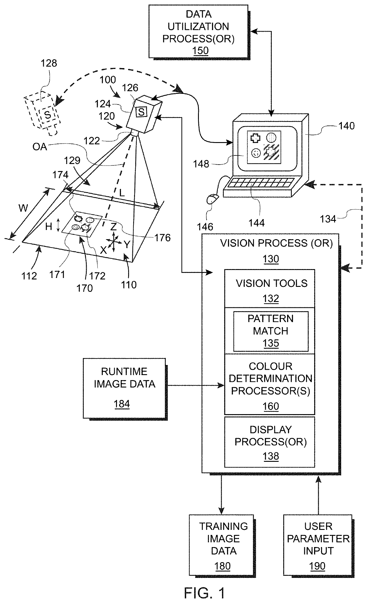
[0022]FIG. 1 shows a machine vision system arrangement (also termed simply, “vision system”) 100 for use in inspecting and / or analyzing features on an object surface in a scene 110 that is imaged within the field of view (FOV) 112 of a vision system camera assembly 120. The camera assembly 120 can be any acceptable arrangement of components and typically includes a lens assembly 122 and a camera body 124 that houses an image sensor (or “imager”) 126, based upon any acceptable imaging technology, such as CCD or CMOS. The imager 126 can be arranged to acquire images in two dimensions (e.g. length L and width W) in an array of image pixels that can be adapted to sense the scene in color and / or another image data form. For example, the camera can also be arranged to acquire three-dimensional (3D) information about the imaged scene within a working space (for example the pyramidal volume 129) that also defines an object height H. A variety of 3D imaging technologies can...


PUM


Abstract

This invention provides a system and method for displaying color match information on an acquired image of an object. A model / pattern having a plurality of color test points at locations of stable color is provided. A display process generates visible geometric shapes with respect to the color test points in a predetermined color. An alignment process aligns features of the object with respect to features on the model so that the geometric shapes appear in locations on the object that correspond to locations on the model. The geometric shapes can comprise closed shapes that surround a region expected to be stable color on the object. Such shapes can define circles, squares, diamonds or any other acceptable closed or open shape that is visible to the user on the display.

Description

RELATED APPLICATION[0001]This application claims the benefit of co-pending U.S. Provisional Application Ser. No. 62 / 647,804, entitled SYSTEM AND METHOD FOR REPRESENTING AND DISPLAYING COLOR ACCURACY IN PATTERN MATCHING BY A VISION SYSTEM, filed Mar. 25, 2018, the teachings of which are expressly incorporated herein by reference.FIELD OF THE INVENTION[0002]This invention relates to machine vision systems and associated methods for alignment and inspection of objects in an imaged scene having color featuresBACKGROUND OF THE INVENTION[0003]Machine vision systems, also termed “vision systems” herein, are used to perform a variety of tasks in a manufacturing environment. In general, a vision system consists of one or more cameras with an image sensor (or “imager”) that acquires grayscale or color images of a scene that contains an object under manufacture. Images of the object can be analyzed to provide data / information to users and associated manufacturing processes. The data produced b...

Claims


Application Information

Patent Timeline
IPC IPC(8): G06T7/90G06T11/20G06T11/00G06V10/56
CPCG06T7/90G06T2200/24G06T11/20G06T11/001G06T2207/10024G06T7/001G06T2207/30108H04N1/6077G06V10/225G06V10/56G06V2201/06
Inventor DAVIS, JASONLIU, ZIHAN HANSBOGAN, NATHANIEL R.
Owner COGNEX CORP
Why Eureka
Try Eureka