
Fuel cell system

a fuel cell and system technology, applied in the direction of electrochemical generators, aqueous electrolyte fuel cells, separation processes, etc., can solve the problems of inability to quickly warm up the fuel cell, the efficiency of the reaction which produces heat at the cathode catalyst is decreased, and the excess liquid water may flow into the fuel cell

Active Publication Date: 2020-02-27
HONDA MOTOR CO LTD
View PDF0 Cites 1 Cited by
  • Summary
  • Abstract
  • Description
  • Claims
  • Application Information

AI Technical Summary

Benefits of technology

The present invention provides a fuel cell system that can effectively warm up the fuel cell and suppress the fuel gas concentration in the exhaust gas by using a gas liquid separator. The gas liquid separator separates the oxygen-containing gas and fuel exhaust gas, which prevents excessive liquid water from entering the fuel cell. Additionally, the separation wall creates a turbulent flow which efficiently stirs the fuel exhaust gas and oxygen-containing gas, inducing chemical reaction and rapid warm-up of the fuel cell.

Problems solved by technology

However, when a fuel exhaust gas containing liquid water is mixed with an oxygen-containing gas, and supplied to a fuel cell, excessive liquid water may flow into the fuel cell.
Further, in the case where the fuel exhaust gas and the oxygen-containing gas are not mixed uniformly, the efficiency of the reaction which produces heat at the cathode catalyst is decreased, and it may not be possible to warm up the fuel cell rapidly.

Method used


Image

  • Fuel cell system
  • Fuel cell system
  • Fuel cell system

Examples


Embodiment Construction

[0020]Hereinafter, a preferred embodiment of a fuel cell system according to the present invention will be described with reference to the accompanying drawings.

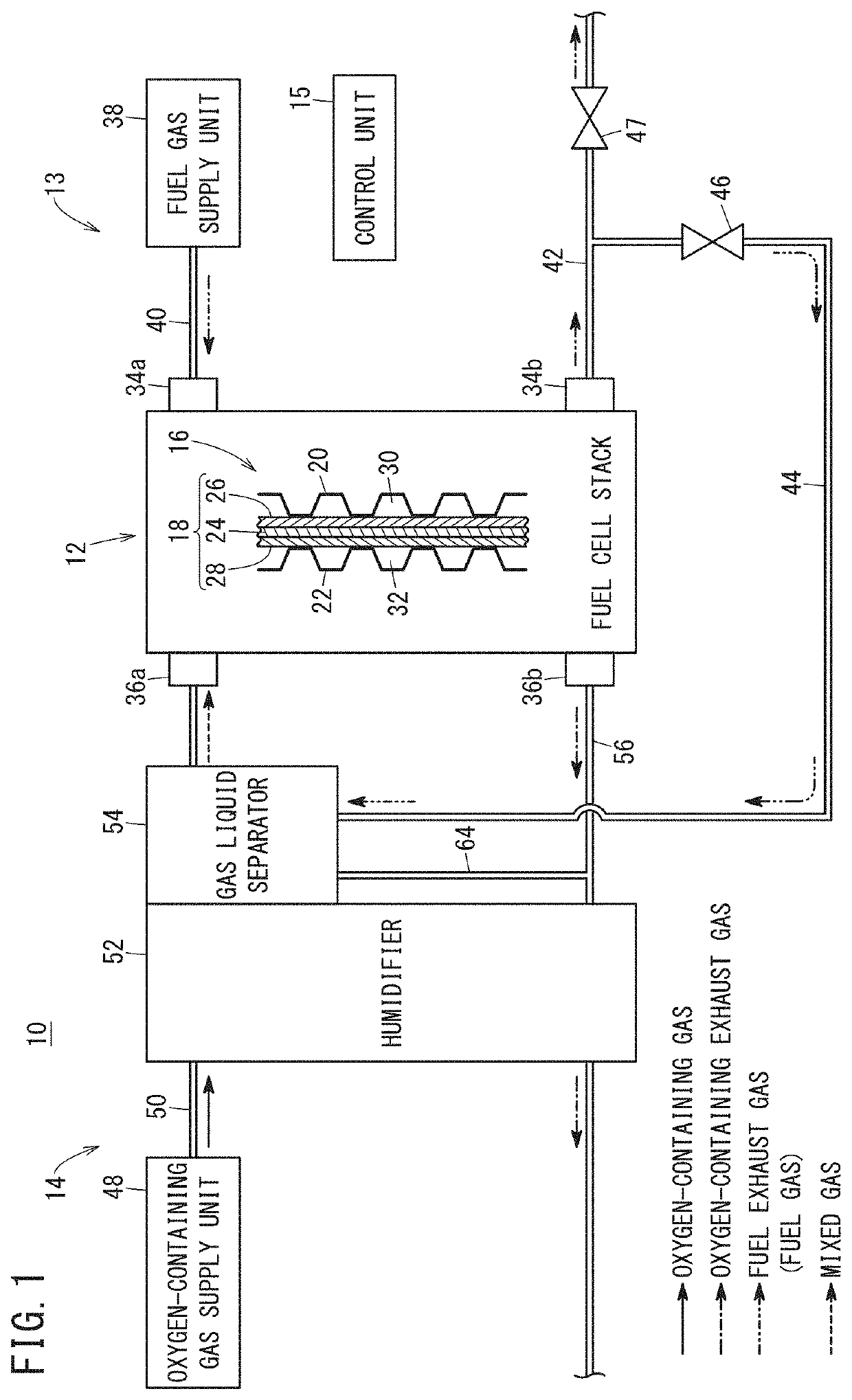
[0021]A fuel cell system 10 shown in FIG. 1 is, e.g., mounted in a fuel cell vehicle (not shown) such as a fuel cell electric automobile. However, it should be noted that the fuel cell system 10 may be mounted in any of various moving objects other than the fuel cell vehicle, or the fuel cell system 10 may be used in stationary applications.

[0022]The fuel cell system 10 includes a fuel cell stack 12 as a fuel cell, a fuel gas supply apparatus 13, an oxygen-containing gas supply apparatus 14, and a control unit 15. Though not shown, the fuel cell system 10 further includes a coolant supply apparatus for cooling the fuel cell stack 12, and a battery, etc.

[0023]The fuel cell stack 12 generates electricity by electrochemical reactions of a fuel gas (e.g., a hydrogen gas) and an oxygen-containing gas (e.g., the air). The fuel cel...


PUM

PropertyMeasurementUnit
specific gravityaaaaaaaaaa
gravityaaaaaaaaaa
proton ion conductivityaaaaaaaaaa

Abstract

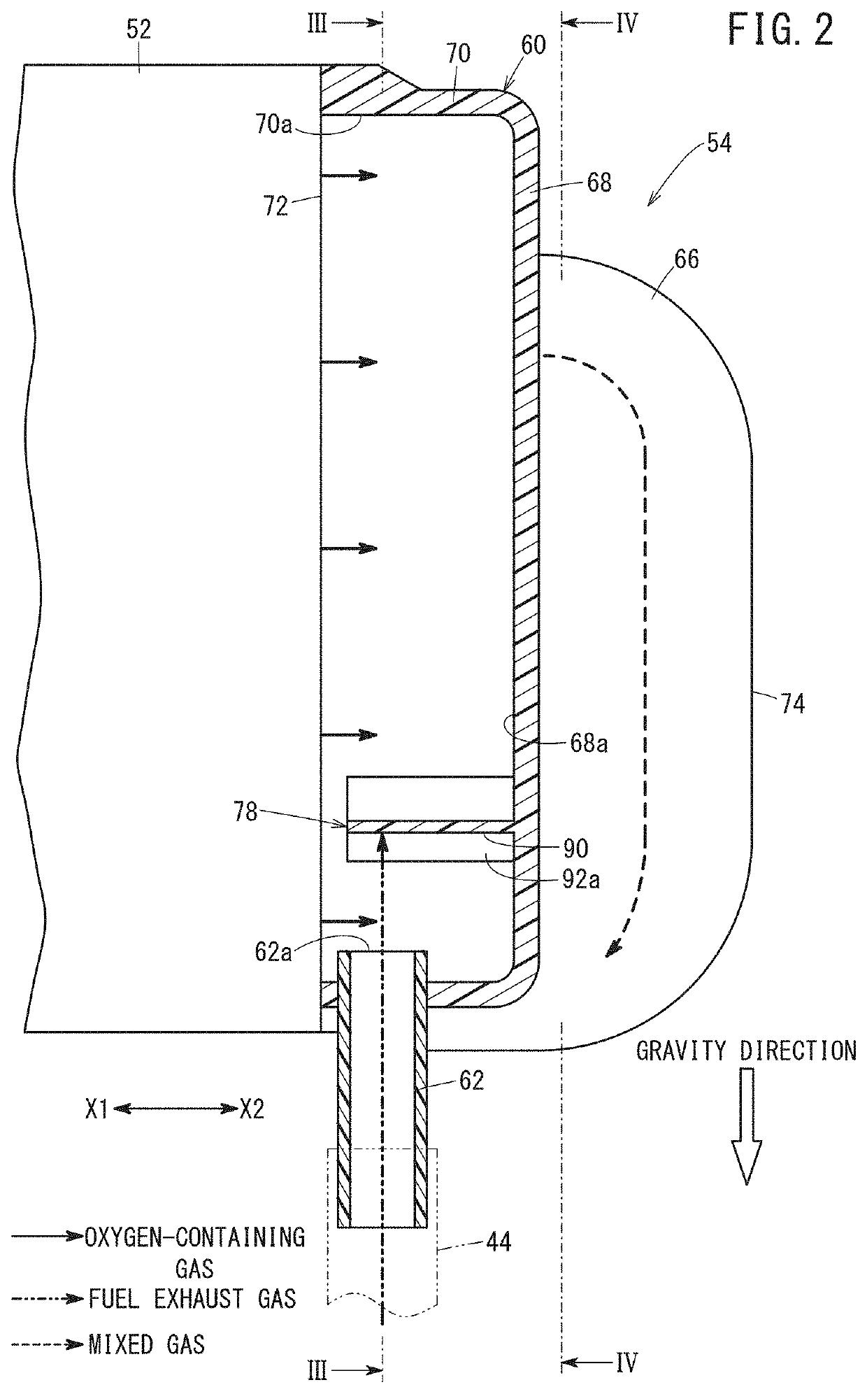
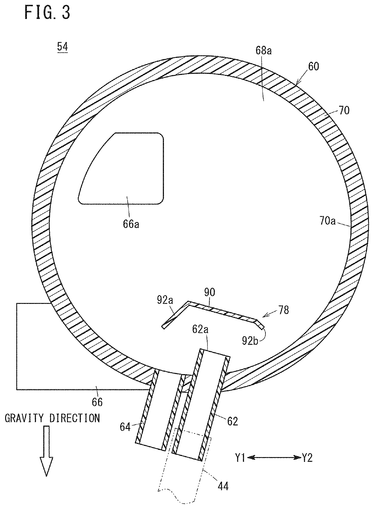
A fuel cell system includes a fuel exhaust gas inlet channel for guiding a fuel exhaust gas containing liquid water discharged from a fuel cell stack to a gas liquid separator provided downstream of a humidifier in an oxygen-containing gas inlet channel. The specific gravity of the fuel exhaust gas is lighter than the specific gravity of the oxygen-containing exhaust gas. An outlet channel of the gas liquid separator includes a stirring booster having a first point and a second point positioned downstream of the first point. The second point is positioned ahead of the first point in the gravity direction.

Description

CROSS-REFERENCE TO RELATED APPLICATION[0001]This application is based upon and claims the benefit of priority from Japanese Patent Application No. 2018-155932 filed on Aug. 23, 2018, the contents of which are incorporated herein by reference.BACKGROUND OF THE INVENTIONField of the Invention[0002]The present invention relates to a fuel cell system including a fuel cell for generating electricity by electrochemical reactions of a fuel gas and an oxygen-containing gas.Description of the Related Art[0003]The fuel cell of this type includes an electrolyte membrane. The electrolyte membrane is a polymer ion exchange membrane of fluorocarbon resin, etc. In the state where the electrolyte membrane contains water, the electrolyte membrane functions as a proton ion conductive electrolyte membrane. In the state where the electrolyte membrane is dried, the proton ion conductivity is decreased, and the output of the fuel cell is decreased undesirably.[0004]In an attempt to address the problem, f...

Claims


Application Information

Patent Timeline
Patent Type & Authority Applications(United States)
IPC IPC(8): H01M8/04089H01M8/08H01M8/0662H01M8/04014
CPCH01M8/04089H01M8/08H01M8/04014H01M8/0662H01M8/04141B01D45/02B01D2247/106Y02E60/50
Inventor HORIUCHI, YUHEIKIMURA, KOICHI
Owner HONDA MOTOR CO LTD
Learn More