Carbon nanotube-based thermal interface materials and methods of making and using thereof
a technology of thermal interface materials and carbon nanotubes, which is applied in the direction of electrical apparatus construction details, semiconductor/solid-state device testing/measurement, instruments, etc., can solve the problems of high contact area at such interfaces between surfaces, early termination of tube growth, and difficulty in growing very long cnts on metal substrates. achieve high levels of complian
- Summary
- Abstract
- Description
- Claims
- Application Information
AI Technical Summary
Benefits of technology
Problems solved by technology
Method used
Image

Examples
example 1
red / Multitiered CNT-Based Thermal Interface Materials (TIMs)
[0224]Methods:
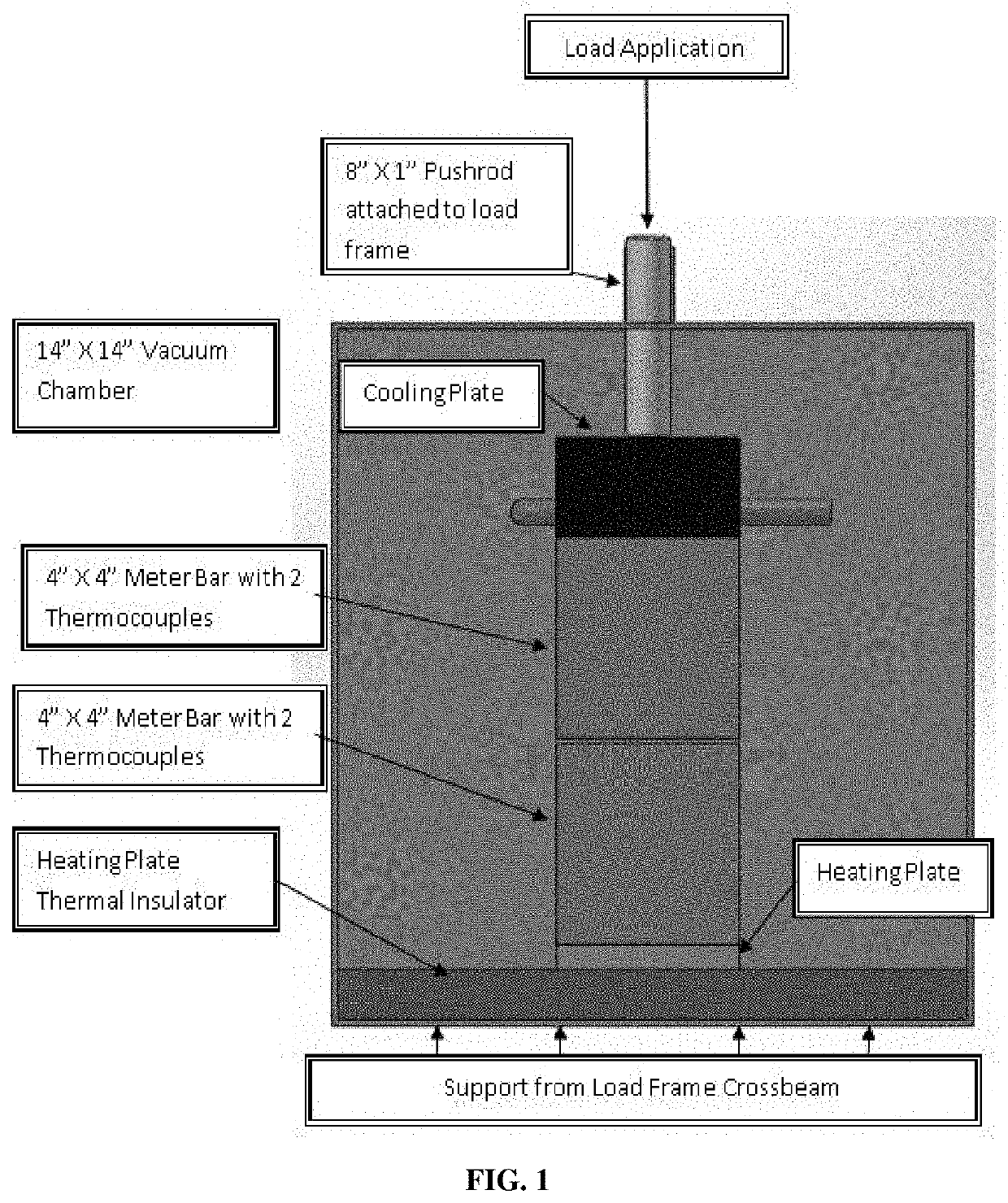
[0225]Thermal Measurement System Design:
[0226]Heat transfer properties for all test specimens were evaluated using a test fixture designed and built based on the methods described in ASTM D5470 “Standard Test Method for Thermal Transmission Properties of Thermally Conductive Electrical Insulation Materials.” It not only allows for deformation of the test specimens but also incorporates a vacuum chamber to minimize conductive and convective heat losses. A schematic diagram of the fixture design is shown in FIG. 1. The vacuum chamber was constructed of stainless steel with an acrylic door, and is capable of maintaining vacuum in the 10−5 torr range. The vacuum chamber sits on the reaction plate of a 1000 lb load frame, with all feedthroughs near the top of the chamber. Thermocouples were fed via a pair of Omega 4-pair feedthroughs (8 thermocouples possible). The cooling tubes possess bulkhead fittings with o-rin...
example 2
red / Multitiered CNT-Based Thermal Interface Materials (TIMs) Containing Polymer or Adhesive
[0249]CNT arrays were grown to nominally 100 μm thickness and fully infiltrated with a soft polyurethane polymer. The thermal resistance of each individual pad was measured using a modified ASTM D570 stepped bar apparatus.
[0250]The individual samples were stacked using various methods, and the thermal resistance of the resulting stack was measured in the same manner as the single tiers.
[0251]First, two individual array samples with measured thermal resistances of 1.37 and 1.5 cm2-K / W respectively were stacked on top of one another. Solvent known to dissolve the polymer that was used to infiltrate the array was placed between the stacks to place the interface in a liquid state. The resulting stack was allowed to dry under pressure until the solvent was fully evaporated. The stack was then measured in the stepped bar system with a resulting resistance of 1.5 cm2-K / W. In this example, the thickne...
example 3
esting of Thermal Interface Materials (TIMs) Sample Fabrication of CNT-TIM Composite
[0253]Vertically aligned carbon nanotubes were grown on 50 μm 1145 H19 aluminum foil coated on both sides with an iron catalyst via low pressure chemical vapor deposition. Acetylene and hydrogen act as precursor gases and growth is performed at 630° C. in order to stay comfortably below the melting temperature of the Al substrate. CNTs are grown to two nominal heights: 15 μm (3 min growth time) or 50 μm (15 minute growth time).
[0254]It is believed that due to the difficulty of repeatably wicking a consistent thickness of bulk paraffin wax into a CNT array, while avoiding excess polymer at the tips, a powder coating technique can more reliably deliver a uniformly thin coating of wax to the CNT tips.
[0255]The synthetic polyethylene waxes used to powder coat the CNTs were supplied in a micronized powder form that is loaded into an Eastwood Dual Voltage HotCoat powder coating gun. Dry air at 5-8 psi was ...
PUM
| Property | Measurement | Unit |
|---|---|---|
| diameter | aaaaa | aaaaa |
| diameter | aaaaa | aaaaa |
| diameter | aaaaa | aaaaa |
Abstract
Description
Claims
Application Information
 - R&D
- Intellectual Property
- Life Sciences
- Materials
- Tech Scout
- Unparalleled Data Quality
- Higher Quality Content
- 60% Fewer Hallucinations
Browse by: Latest US Patents, China's latest patents, Technical Efficacy Thesaurus, Application Domain, Technology Topic, Popular Technical Reports.
© 2025 PatSnap. All rights reserved.Legal|Privacy policy|Modern Slavery Act Transparency Statement|Sitemap|About US| Contact US: help@patsnap.com