Two-way valve

Active Publication Date: 2020-02-27
SMC CORP
View PDF0 Cites 1 Cited by
  • Summary
  • Abstract
  • Description
  • Claims
  • Application Information

AI Technical Summary

Benefits of technology

The present invention is about a two-way valve that prevents the production of particles and increases the durability of the diaphragm valve by reducing impact caused by contact between the diaphragm valve and the valve seat portion. This is achieved by designing an annular projection on the diaphragm valve that comes into contact with the flat seat surface of the valve seat portion and absorbing the impact by an elastic member attached at the back of the annular projection. The valve element surface is formed into a thin film shape to enable easy deformation, but it may tear easily due to excessive stretches caused by repeated deformation along the shapes of the projections on the valve seat portion. The elastic member prevents contact between the projections on the valve seat portion and the diaphragm valve at different positions, thereby increasing the durability of the diaphragm valve.

Problems solved by technology

However, the valve element surface of the diaphragm described in Japanese Laid-Open Patent Publication No. 2015-215028 is formed into a thin film shape in order to be deformed easily, and may tear easily due to excessive stretches caused by repeated deformation along the shapes of the projections on the valve seat portion.
Moreover, when excessive stretches including permanent deformation occur in the valve element surface, the projections on the valve seat portion may come into contact with the valve element surface at different positions, thereby causing particle production and a reduction in durability due to fluid leakage.

Method used


Image

  • Two-way valve
  • Two-way valve
  • Two-way valve

Examples


first embodiment

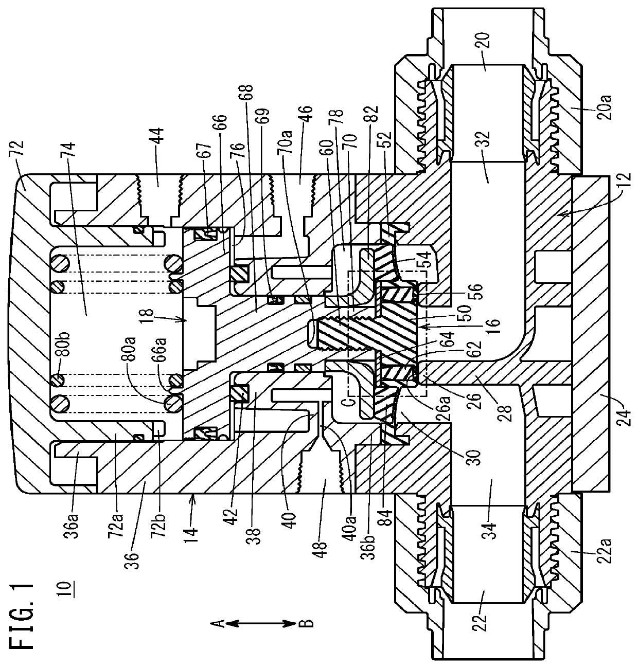
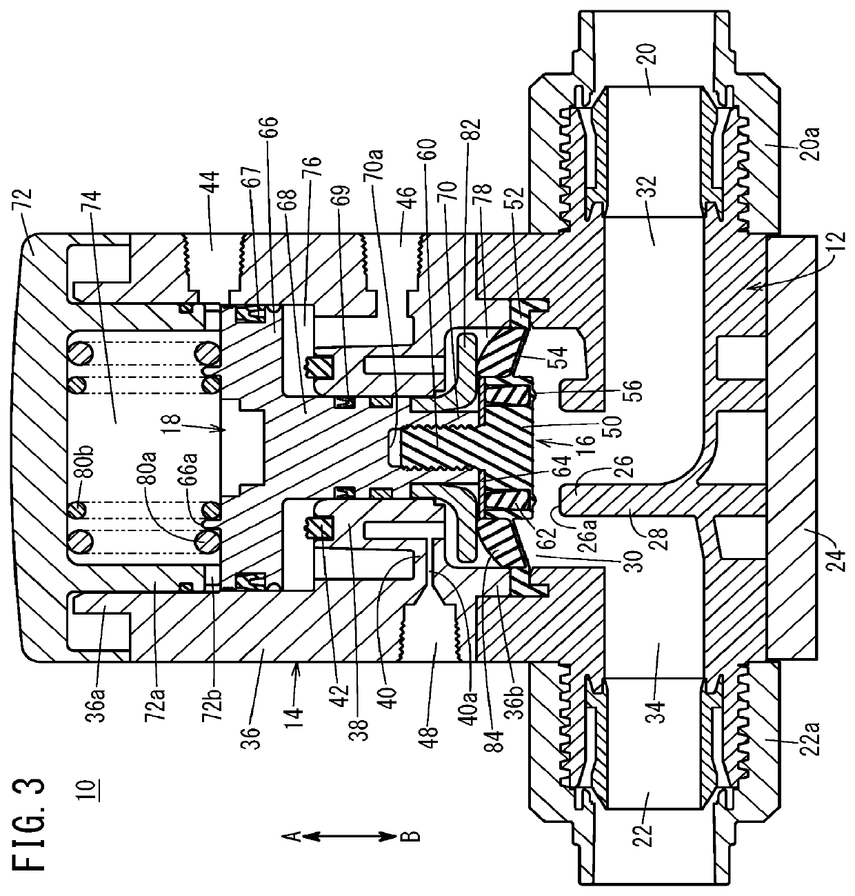
[0020]A two-way valve 10 according to a first embodiment of the present invention will now be described with reference to FIGS. 1 to 5. The two-way valve 10 includes a body part 12 having a primary port 20 and a secondary port 22 formed therein, a bonnet 14 joined to an upper portion of the body part 12, a diaphragm valve 16, and a piston 18. The body part 12 and the bonnet 14 constitute the valve body.

[0021]The body part 12 is made of a metal material such as aluminum alloy or a resin material such as a fluororesin (e.g., PFA). In the body part 12, the primary port 20, into which pressurized fluid flows, and the secondary port 22, from which the pressurized fluid flows out, are coaxially aligned to face each other. A primary coupling 20a for tube connection is attached to the primary port 20, and thereby the primary port 20 is connected to a first pressurized fluid supply source (not illustrated) via a tube. A secondary coupling 22a for tube connection is attached to the secondary ...

second embodiment

[0050]Next, a two-way valve 90 according to a second embodiment of the present invention will be described with reference to FIGS. 6 to 8. The second embodiment is different from the first embodiment in terms of the structure of the damper member and the surrounding structure. In the two-way valve 90 according to the second embodiment, the same reference numerals and symbols are used for components identical or equal to those in the two-way valve 10 described above, and the detailed descriptions will be omitted.

[0051]A damper member 92 according to the second embodiment is configured as a coned-disk spring. An annular protrusion 93 is formed on the upper end surface of the inner tubular portion 38 of the bonnet 14, and a first tapered surface 94 is formed inside the annular protrusion 93. The first tapered surface 94 is inclined downward toward the inside. The damper member 92 is disposed inside the annular protrusion 93, and the outer peripheral edge of the damper member 92 engages...


PUM


Abstract

A two-way valve configured to switch between a communication state and a non-communication state of between a primary port and a secondary port includes a valve body having the primary port and the secondary port and containing a valve seat portion therein, a diaphragm valve supported inside the valve body so as to be brought into contact with and separated from the valve seat portion, and a drive mechanism configured to displace the diaphragm valve. The diaphragm valve includes an annular projection facing a flat seat surface of the valve seat portion and an elastic member attached at the back of the annular projection.

Description

CROSS-REFERENCE TO RELATED APPLICATIONS[0001]This application is based upon and claims the benefit of priority from Japanese Patent Application No. 2018-155928 filed on Aug. 23, 2018, the contents all of which are incorporated herein by reference.BACKGROUND OF THE INVENTIONField of the Invention[0002]The present invention relates to a two-way valve configured to switch between communication state and non-communication state of between a primary port and a secondary port, by displacement of a diaphragm valve.Description of the Related Art[0003]Heretofore, there have been known two-way valves including a valve body containing therein primary and secondary ports and a diaphragm valve, wherein the diaphragm valve is configured to open and close a communication path between the primary and secondary ports (for example, see Japanese Patent No. 3701367).[0004]In such two-way valves, techniques for reducing impact caused when the diaphragm valve comes into contact with a valve seat portion ...

Claims


Application Information

Patent Timeline
IPC IPC(8): F16K7/16
CPCF16K7/16F16K7/17F16K27/0236F16K31/122F16F1/322
Inventor DOI, YOSHITADAOKITA, YUZURUSUZUKI, TAKAMITSUNAGATA, AKINORI
Owner SMC CORP
Why Eureka
Try Eureka