Methods for the removal of co2 from atmospheric air or other co2-containing gas in order to achieve co2 emissions reductions or negative co2 emissions
a technology of atmospheric air and co2 containing gas, which is applied in the direction of pigmenting treatment, liquid hydrocarbon mixture production, inorganic chemistry, etc., can solve the problems of low societal acceptance of underground co2 sequestration, and achieve the effects of high co2 purity, reduced co2 emissions, and improved co2 sequestration efficiency
- Summary
- Abstract
- Description
- Claims
- Application Information
AI Technical Summary
Benefits of technology
Problems solved by technology
Method used
Image

Examples
example 1
very from Produced Carbon and Hydrogen
[0080]The carbon produced by cracking of methane is leaving the cracking reactor as either hot carbon aerosol or hot carbon particles, which roughly have the same temperature as the methane cracking reactor temperature. The carbon product particles or carbon product aerosol have to be cooled before final collection e.g. through water sprays. The heat transferred from the hot particles or hot aerosol to the water can be collected as steam or hot water, which can then be subsequently used to e.g. supply heat for the operation of the DAC plant. The heat capacity of carbon is 8.5 J / mol / K. Assuming the methane cracking reactor is operated at 1550° C., which is also roughly the temperature of the carbon product, and the carbon product is subsequently cooled to 100° C., the heat which can be recovered from cooling the carbon product is (8.5 J / mol carbon / K*1450K)=12.3 kJ / mol carbon.
[0081]Similarly to the carbon product the hydrogen leaving the cracking ...
example 2
very from Methanation
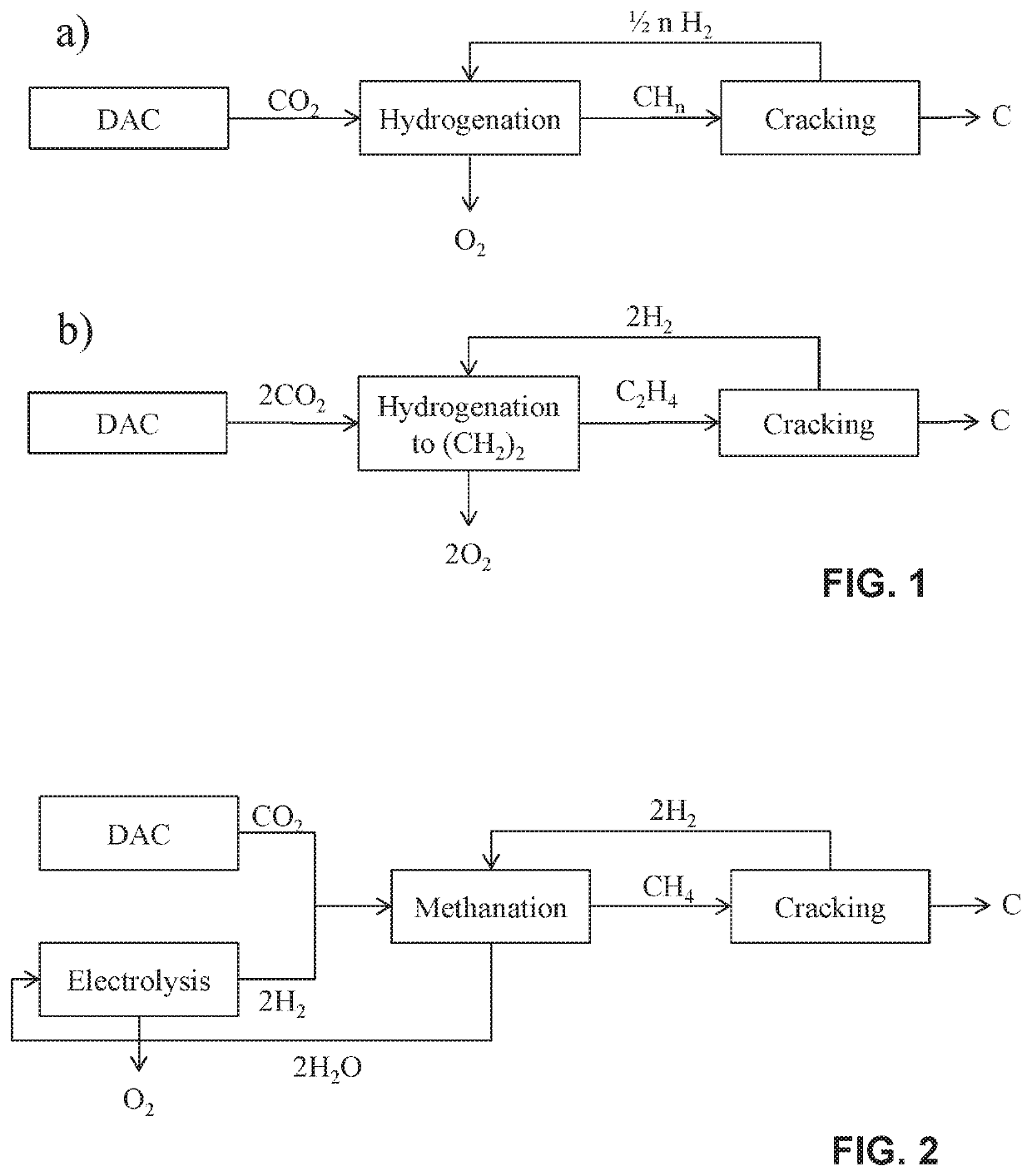
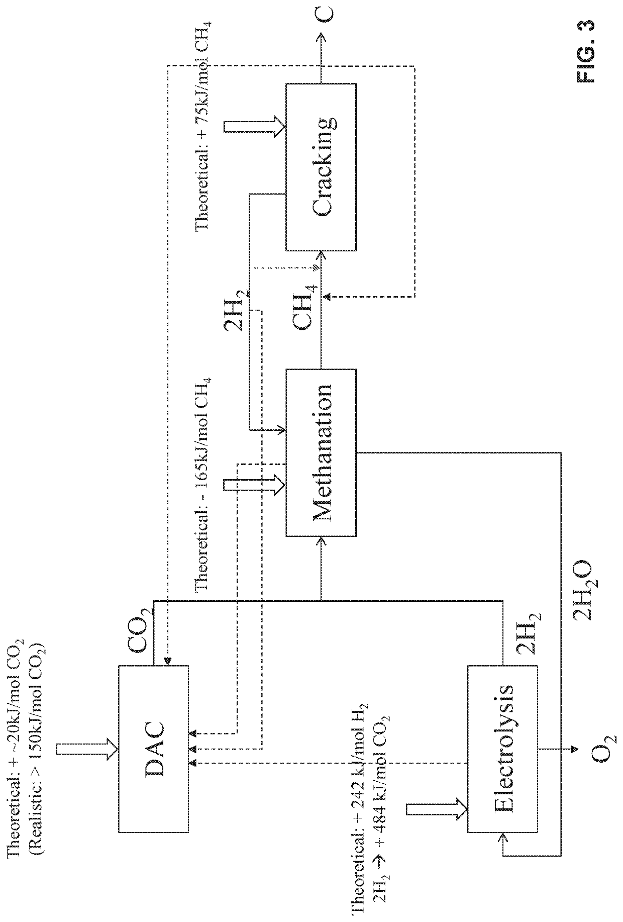
[0083]Methanation proceeds according to the following reaction scheme:
CO2+4H2→2H2O+CH4
[0084]Methanation is an exothermic reaction providing 165 kJ of heat per mole of CH4 produced. Depending on the type of methanation used, the heat is released at different temperatures, e.g. if chemical methanation system is used the reaction occurs at a temperature of 150-300° C. and if biological methanation system is used the reaction occurs at a temperature of 50-100° C. Chemical methanation systems are especially interesting since heat release is at a temperature sufficiently high, so that the supplied heat can be used to provide heat for the DAC plant, as described in Example 1.
example 3
of Hydrogen from Methane Cracking to Methanation Reactor
[0085]The methane cracking reaction, e.g. according to the process as proposed by Geissler et al in Chemical Engineering Journal 299 (2016) 192-200, yields two moles of hydrogen per one mole of carbon produced, according to the following reaction scheme:
PUM
| Property | Measurement | Unit |
|---|---|---|
| Temperature | aaaaa | aaaaa |
| Temperature | aaaaa | aaaaa |
| Temperature | aaaaa | aaaaa |
Abstract
Description
Claims
Application Information
 - R&D
- Intellectual Property
- Life Sciences
- Materials
- Tech Scout
- Unparalleled Data Quality
- Higher Quality Content
- 60% Fewer Hallucinations
Browse by: Latest US Patents, China's latest patents, Technical Efficacy Thesaurus, Application Domain, Technology Topic, Popular Technical Reports.
© 2025 PatSnap. All rights reserved.Legal|Privacy policy|Modern Slavery Act Transparency Statement|Sitemap|About US| Contact US: help@patsnap.com