
Intelligent constant temperature system for thermal spring water

A technology of constant temperature system and hot spring water, which is applied in the system of controlling the constant temperature of hot spring water in hot spring pools, and the field of utilization of constant temperature in hot spring pools, which can solve the problem of inaccurate control of hot spring water temperature, precise control of hot spring water temperature, and influence on hot spring water. Bath comfort and other issues, to achieve the effect of saving hot spring water resources, high cost performance, and excellent performance

Inactive Publication Date: 2018-03-02
陈启云
View PDF0 Cites 0 Cited by
  • Summary
  • Abstract
  • Description
  • Claims
  • Application Information

AI Technical Summary

Problems solved by technology

[0002] Because hot spring water is rich in mineral elements, it is very helpful to human health. Soaking in hot springs has become the only choice for people in modern society to relax and maintain health. However, most hot spring operators use two methods to solve the problem of temperature drop in the process of bathing in hot spring water. Solution, one is to directly supplement high-temperature water to keep the temperature constant. This method not only wastes hot spring water resources, but also cannot accurately control the temperature of hot spring water, which directly affects the comfort of bathing. The other is conventional circulation heating through plate heat exchangers. , this method is improved compared with the direct replenishment of water and constant temperature, and saves hot spring water resources, but it still cannot control the temperature of hot spring water stably and accurately

Method used


Image

  • Intelligent constant temperature system for thermal spring water

Examples


Embodiment Construction

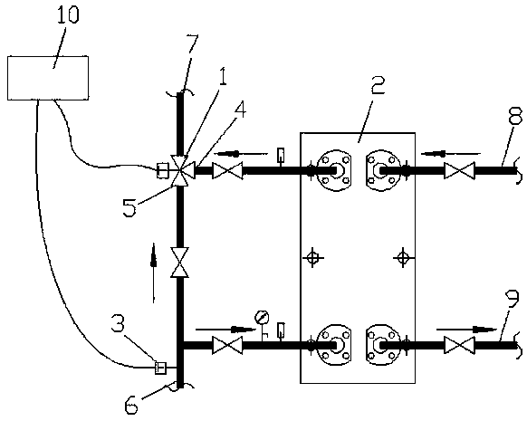
[0014] Such as figure 1 As shown, the hot spring water intelligent constant temperature system includes a three-way electric valve 1 , a plate heat exchanger 2 and a temperature sensor 3 . The water inlet Ⅰ4 of the three-way electric valve 1 is connected to the water outlet on the side of the plate heat exchanger 2 through a pipeline, and the water inlet Ⅱ5 of the three-way electric valve 1 and the water inlet on the side of the plate heat exchanger 2 are connected to the hot spring pool The return pipe 6 is connected (the return water from the hot spring pool is divided into two before entering the plate heat exchanger 2, one way enters the plate heat exchanger 2 to heat up and then connects to the water inlet I4 of the three-way electric valve 1, and the other directly connects to Water inlet II5 of three-way electric valve 1). The temperature sensor 3 is arranged on the return water pipe 6 of the hot spring bubble pool to monitor the return water temperature of the bubble ...


PUM


Abstract

The invention discloses an intelligent constant temperature system for thermal spring water. The system comprises a three-way electric valve, a plate heat exchanger and a temperature sensor; a water inlet I of the three-way electric valve is connected with a water outlet at one side of the plate heat exchanger through a pipeline; a water inlet II of the three-way electric valve and a water inlet at one side of the plate heat exchanger are both connected with a thermal spring pool water return pipe; the temperature sensor is installed on the thermal spring pool water return pipe; a water outletof the three-way electric valve is connected with a thermal spring pool water distributing pipe; the other side of the plate heat exchanger is provided with a heating medium water inlet pipe and a heating medium water return pipe. According to the invention, there is no need of additional supplement of thermal spring water so as to effectively save the thermal spring water resources; by means ofthe system, constant temperature thermal spring water supply can be guaranteed to increase comfort level for users; from temperature check, signal transmission, valve operation, the whole constant temperature process is controlled by control box, which improves management efficiency; compared with the existing system, this system has the same cost, better performance and high cost performance.

Description

technical field [0001] The invention relates to a constant temperature utilization technology of a hot spring pool, specifically a system capable of controlling the constant temperature of hot spring water in a hot spring pool, and belongs to the technical field of hot spring water control. Background technique [0002] Because hot spring water is rich in mineral elements, it is very helpful to human health. Soaking in hot springs has become the only choice for people in modern society to relax and maintain health. However, most hot spring operators use two methods to solve the problem of temperature drop in the process of bathing in hot spring water. Solution, one is to directly supplement high-temperature water to keep the temperature constant. This method not only wastes hot spring water resources, but also cannot accurately control the temperature of hot spring water, which directly affects the comfort of bathing. The other is conventional circulation heating through plat...

Claims


Application Information

Patent Timeline
Patent Type & Authority Applications(China)
IPC IPC(8): F24H9/20F24H9/12
CPCF24H9/2007F24H9/13
Inventor 陈启云
Owner 陈启云
Learn More