
Submicron fusion devices, methods and systems

a technology of fusion devices and submicron particles, applied in the field of submic, can solve the problems of large fusion devices and systems, large energy loss in conventional fusion systems, complex, difficult to manage, etc., and achieve the effects of suppressing radiation losses, greatly reducing radiative losses, and suppressing electron mobility

Active Publication Date: 2020-02-13
ALPHA RING INT LTD
View PDF1 Cites 0 Cited by
  • Summary
  • Abstract
  • Description
  • Claims
  • Application Information

AI Technical Summary

Benefits of technology

The present invention is about a new method for controlled submicron fusion, which can effectively suppress radiation losses and achieve higher efficiency in energy production. The invention uses a high-density, lightly ionized, and colder plasma, which reduces electron mobility and the input energy required. The plasma can also become highly conductive or even a superconductor, lowering the resistive loss and the input energy required. The invention may generate particles during operation, which may provide benefit to the device's function or improve the ionization or working material. The key feature of the new fusion concept is the screening effect of electrons around the neutrals, which creates stronger screening effects and could create a sustainable fusion process for energy production.

Problems solved by technology

The art's pursuit of the Lawson criterion, or substantially similar paradigms, has led to fusion devices and systems that are large, complex, difficult to manage, expensive, and economically unviable.
In particular, a major source of energy loss in conventional fusion systems is radiation due to electron bremsstrahlung and cyclotron motion as mobile electrons interact with ions in the hot plasma.
Because the conventional thinking holds that high temperatures and strongly ionized plasma are required, it was further believed in the art that inexpensive physical containment of the reaction was impossible.
Accordingly, methods being pursued in the art are directed to complex and expensive schemes to contain the reaction, such as those used in magnetic confinement systems (e.g., the ITER tokamak) and in inertial confinement systems (e.g., NIF laser).
Accordingly, there has been a long-standing and unfulfilled need for a controlled fusion reaction, and the clean energy and other benefits and beneficial uses that are associated with such a reaction.
While battery technologies and other power sources have been rapidly evolving and becoming smaller, and smaller, in many instances they have failed to keep up with the needs of smaller and smaller devices, and the need for having power supplies that do not readily become depleted.
Unfortunately, in many cases, battery technology may be becoming the limiting factor to the further advancement of these small electronic technologies.

Method used


Image

  • Submicron fusion devices, methods and systems
  • Submicron fusion devices, methods and systems
  • Submicron fusion devices, methods and systems

Examples


example 1

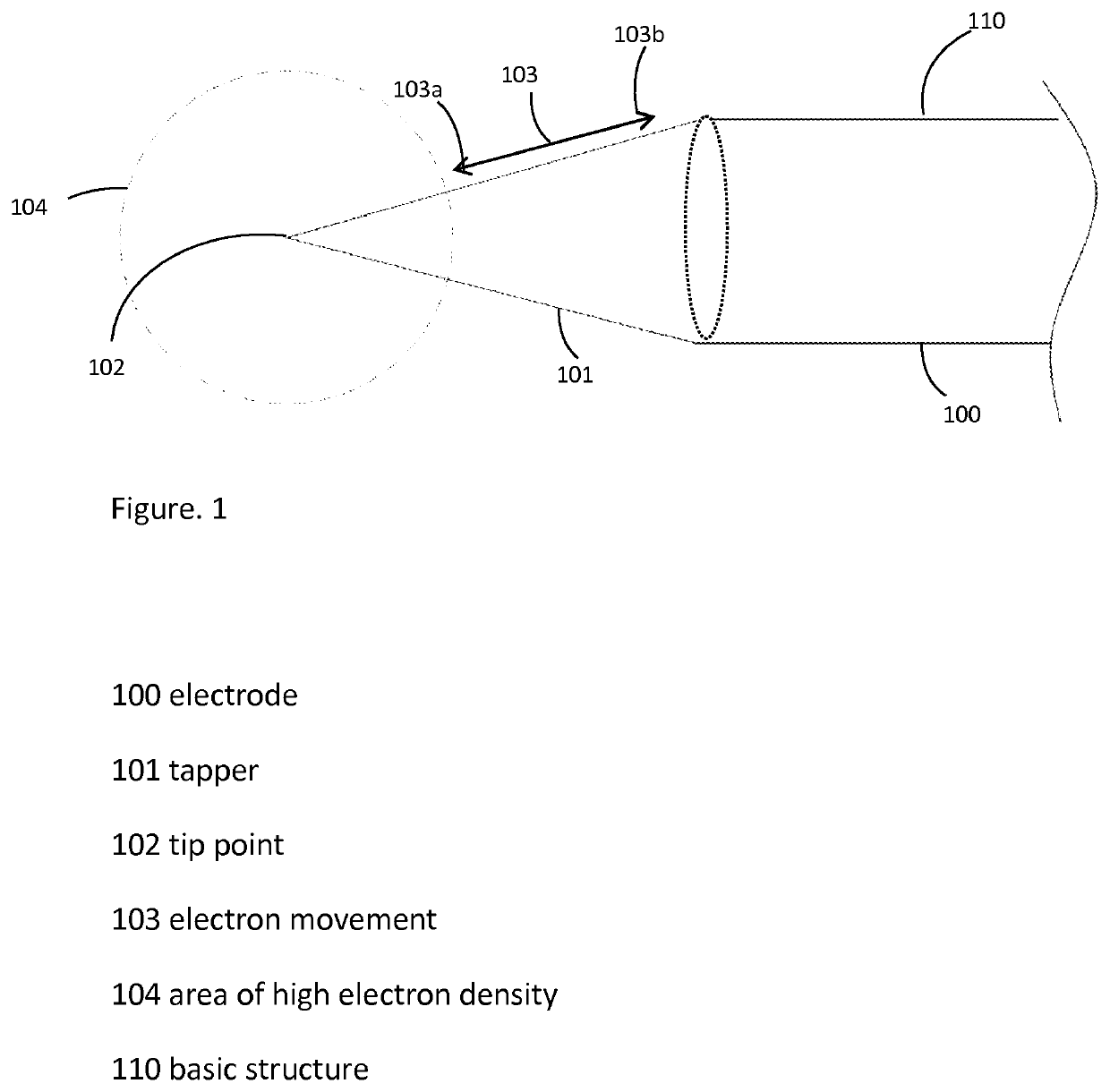
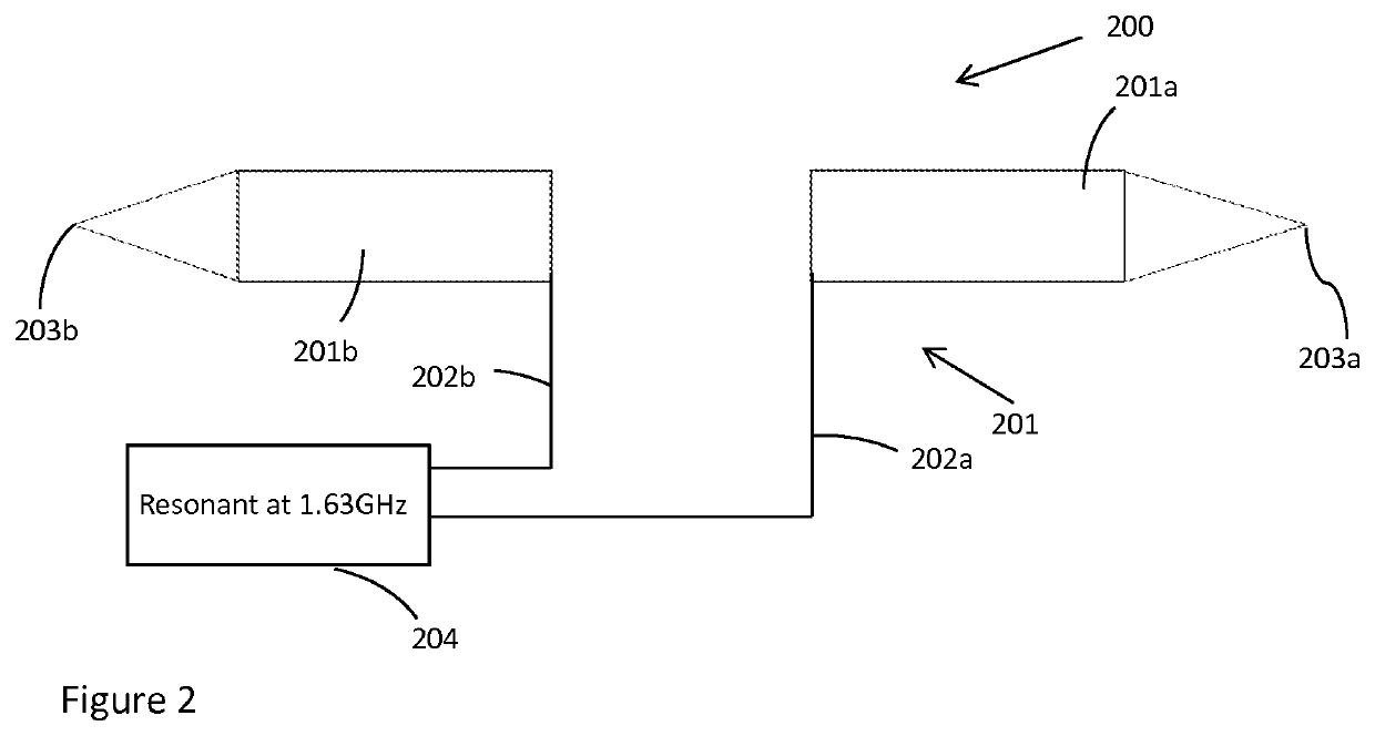
[0085]Turning to FIG. 2 there is shown a schematic of a submicron controlled fusion device 200. The device 200 has an electrode 201a, which is part of the base structure 201. The device 200 has a second electrode 201b, which is also part of the base structure 201. The electrodes 201a and 201b have substructures that contain the fusion fuel. The electrodes 201a, 201b, have tips 203a, 203b, which are discontinuities. Electrode 201a is connected to high density electron generator 204 by lead line 202a. Electrode 201b is connected to high density electron generator 204 by lead line 202b. The high density electron generator 204, in the embodiment of this example is an RF generator operating at 1.63 GHz. The dimensions for the device 200 are provided in the figure and are in inches.

[0086]Turning to FIG. 3 there is shown a schematic representation of the electron fields that will be generated by the device 200. FIG. 3 is a plan view, looking down the y-axis, of the tip 203b and electrode 2...

example 2

[0087]The embodiment of example 1, has the electrodes made from palladium, and are coated with a thin layer of gold. The fusion fuel is a 50:50 mixture of hydrogen-1 and deuterium, and loaded to a particle density of 1022 / cc.

example 3

[0088]The device of Example 2 has been operated in a cloud chamber to test the behavior of electrons. According to theory and past experiments the cloud chamber will show the emission of fusion product particles from the electrodes. The fusion products will include helium-3.


PUM


Abstract

Methods, apparatus, devices, and systems for creating, controlling, conducting, and optimizing fusion activities of nuclei. In particular, the present inventions relate to, 5 among other things, fusion activities that are conducted individually or collectively on a very small scale, preferably on the nano-scale or smaller such as pico to femto scales, for the utilization of energy produced from these activities in smaller devices and for aggregation into larger devices.

Description

PRIORITY DATA[0001]An Application Data Sheet is filed concurrently with this specification as part of the present application. Each application that the present application claims benefit of or priority to as identified in the concurrently filed Application Data Sheet is incorporated by reference herein in its entirety and for all purposes.BACKGROUND OF THE INVENTIONField of the Invention[0002]The present inventions relate to methods, apparatuses, devices, and systems for creating, controlling, conducting, and optimizing fusion activities of nuclei. In particular, the present inventions relate to, among other things, fusion activities that are conducted individually or collectively on a very small scale, preferably on the nano-scale or smaller such as pico to femto scales, for the utilization of energy produced from these activities in smaller devices and for aggregation into larger devices.[0003]Controlled fusion devices, methods and systems are taught and disclosed in US Patent Ap...

Claims


Application Information

Patent Timeline
Patent Type & Authority Applications(United States)
IPC IPC(8): G21B3/00
CPCG21B3/00Y02E30/10
Inventor WONG, ALFRED Y.
Owner ALPHA RING INT LTD
Learn More