
Lc duplex connector

a duplex connector and connector technology, applied in the direction of optical elements, coupling device connections, instruments, etc., can solve the problems of increasing equipment cost and affecting operation efficiency, and achieve the effect of reducing equipment cost, smooth removal, and increasing the utility of the surface area provided by the cabinet panel

Active Publication Date: 2020-02-13
HUIZHOU FIBERCAN IND CO LTD
View PDF0 Cites 2 Cited by
  • Summary
  • Abstract
  • Description
  • Claims
  • Application Information

AI Technical Summary

Benefits of technology

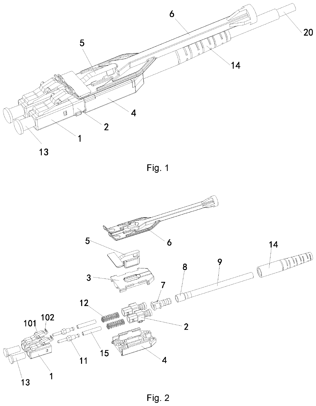
The present invention aims to provide a LC duplex connector that can be easily disassembled, increasing the utilization of surface area provided by the cabinet panel. The connector includes an intermediate panel and a pulling rod with pulling hooks that work with corresponding reverse hooks on a press strip. Pulling the pull rod results in disengagement from the LC adaptors, allowing for smooth removal without the need for additional space between the connectors and the adaptors. The connector is convenient to switch and disassemble, improving operational efficiency.

Problems solved by technology

Accordingly, utility of the surface area provided by the cabinet panel is ineffective, thereby increasing the cost of the equipment.
Also, the above configurations are inconvenient for removing and switching LC connectors, thereby affecting the operation efficiency,

Method used


Image

  • Lc duplex connector
  • Lc duplex connector
  • Lc duplex connector

Examples


Embodiment Construction

[0029]In order that the objects, technical solutions and advantages of the present invention are more clearly understood, the present invention will be described further in detail below with reference to some embodiments and the figures. It should be understood that, the embodiments as will be described are only intended to illustrate the present invention and are not intended to limit the present invention.

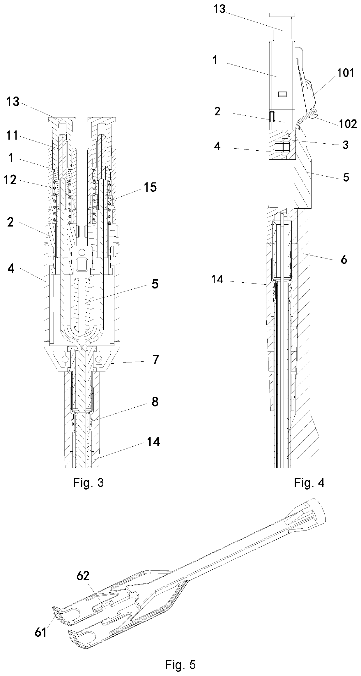
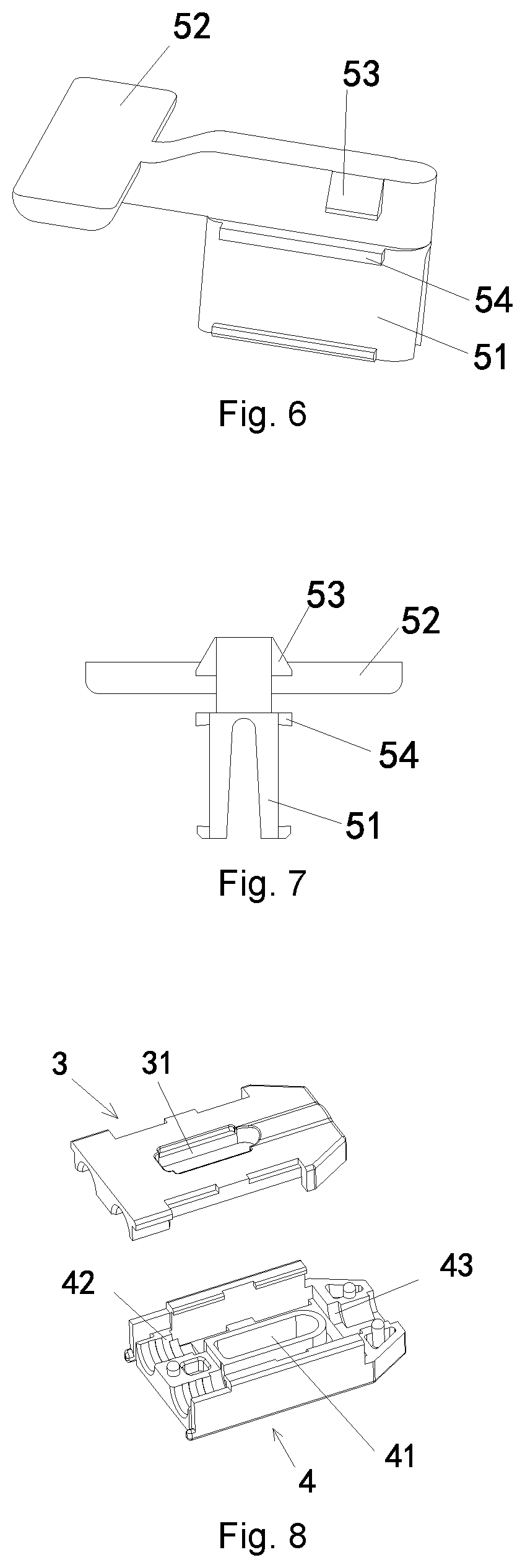
[0030]FIGS. 1-11 illustrate a first embodiment of the LC duplex connector according to the present invention, comprising front casings 1, rear casings 2, an upper cover panel 3 and a lower cover panel 4. Each of the front casings 1 is provided with a press strip 101; a fastening point (not shown in the figures, for fastening with the LC adaptors) is provided on the press strip 101; the LC duplex connector also comprises an intermediate panel 5 and a pull rod 6; a first through hole 31 and a second through hole 41 are provided on the upper cover panel 3 and the lower cover panel 4...


PUM


Abstract

An LC duplex connector having an intermediate panel and a pulling rod; a first through hole and a second through hole are provided on an upper cover panel and a lower cover panel respectively: an elastic arm is provided on the intermediate panel; the elastic arm is inserted into the first and second through holes to fix the intermediate panel with respect to the upper and lower cover panels; the pull rod is installed on the intermediate panel and is axially slidable; the press strip is provided with a reverse hook; the pull rod is provided with pulling hooks each being cooperative with a corresponding reverse hook. When pulling the pull rod, the pulling hooks of the pull rod apply a downward force against the reverse hooks, thus driving the Dress strips to move downwardly to disengage the LC duplex connector from the concealed fasteners of the LC adaptors.

Description

BACKGROUND OF THE INVENTION[0001]The present invention relates to the technical field of optical fiber communication, and more specifically relates to an LC duplex connector.[0002]LC connector is a kind of optical fiber coupler. The LC connector according to the prior art is provided with a press strip and a fastening point on the press strip. The LC connector is fixed with an LC adaptor via a concealed fastener. If it is desired to disconnect the connected LC connector and the LC adaptor, the user is required to press the press strip of the LC connector by using a finger before the LC connector can be removed. Therefore, when LC connectors and LC adaptors are installed on a cabinet panel, LC connectors and LC adaptors installed on an upper row of the cabinet panel have to be spaced apart by a certain distance from the LC connectors and LC adaptors installed on a bottom row, so that sufficient space is allowed for the fingers of the user to press the press strips of the LC connector...

Claims


Application Information

Patent Timeline
IPC IPC(8): G02B6/38H01R13/506H01R13/633
CPCG02B6/3885G02B6/3858G02B6/3825H01R13/506G02B6/3893H01R13/6335G02B6/3879G02B6/36
Inventor LI, YAOLE
Owner HUIZHOU FIBERCAN IND CO LTD
Learn More