Eureka AIR delivers breakthrough ideas for toughest innovation challenges, trusted by R&D personnel around the world.

Real-time data processing pipeline and pacing control systems and methods

a real-time data and message processing and control system technology, applied in the field of data processing and control architectures, can solve problems such as substantial scaling challenges and increase difficulties

Active Publication Date: 2020-01-23
MICROSOFT TECH LICENSING LLC
View PDF5 Cites 3 Cited by
  • Summary
  • Abstract
  • Description
  • Claims
  • Application Information

AI Technical Summary

Benefits of technology

The patent describes a computer-implemented method for providing visual information to user applications running on a client device. The system receives a call for visual information from the user application and determines the likelihood that the visual information will be viewable within the user application's viewport in real-time. The system then selects the most suitable source of visual information and provides it to the user application. The method also includes a publish / subscribe and message queueing subsystem that receives a real-time stream of transactions and creates jobs to aggregate data from these transactions. Additionally, the system tracks the viewability of visual information over time and provides historical viewability information to the view predictor subsystem to determine when the visual information will be viewable within the user application's viewport. The technical effect of the patent is to optimize the viewability of visual information and enhance the user experience.

Problems solved by technology

Data processing and storage systems that have to address thousands of simultaneous transactions within tens or hundreds of milliseconds face substantial challenges in scaling while keeping latency at a minimum.
These difficulties increase when the results of data processing operations depend on data that is continuously collected from many remote clients.

Method used


Image

  • Real-time data processing pipeline and pacing control systems and methods
  • Real-time data processing pipeline and pacing control systems and methods
  • Real-time data processing pipeline and pacing control systems and methods

Examples


Embodiment Construction

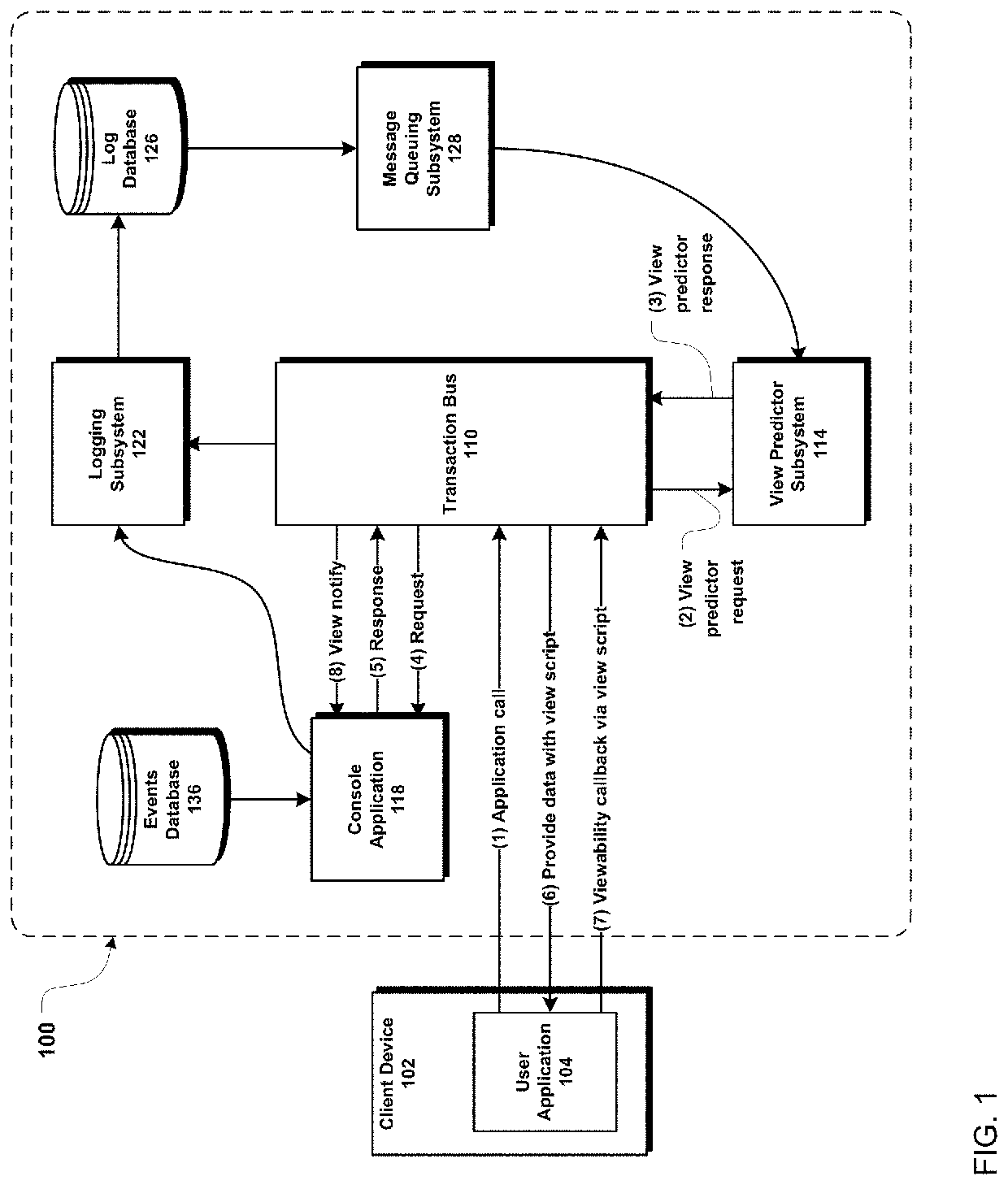
[0018]FIG. 1 depicts an example high-level system 100 including a real-time data processing pipeline architecture, according to one implementation. A client device 102, such as a smartphone, laptop, desktop computer, tablet, or other computing device, executes a user application 104, such as a web browser or desktop or mobile operating system native application. Upon occurrence of an event on the client device 102 (e.g., opening user application 104, browsing to a webpage within user application 104, etc.), user application 104 makes a call, over a network (e.g., the internet, mobile phone network, etc.), to transaction bus 110 within the system 100. The call can include a request for data, for example, a request to receive visual information such as an image or video.

[0019]Transaction bus 110 executes on one or more physical servers within one or more data centers, and interfaces with various components within system 100 to cause the performance of real-time data processing operati...


PUM


Abstract

A data processing system includes a transaction bus, a console application in communication with the transaction bus, and a view predictor subsystem in communication with the transaction bus. The transaction bus receives, from a user application executing on a client device, a call for visual information to be provided to the user application. The view predictor subsystem determines a likelihood that the visual information will be viewable within a viewport of the user application, and a plurality of respective values for a plurality of sources of the visual information are computed based on the likelihood and a respective priority for each source. The console application provides to the transaction bus the set of potential sources of the visual information, and the transaction bus selects, based on the computed values, one of the potential sources of the visual information to be the result, which is provided to the user application.

Description

TECHNICAL FIELD[0001]The present disclosure relates generally to data processing and control architectures and, more particularly, to a real-time data and message processing system and corresponding pacing control methods.BACKGROUND[0002]Data processing and storage systems that have to address thousands of simultaneous transactions within tens or hundreds of milliseconds face substantial challenges in scaling while keeping latency at a minimum. These difficulties increase when the results of data processing operations depend on data that is continuously collected from many remote clients. Accordingly, there is a need to provide real-time data processing systems with high-performance data storage and streaming architectures that address the unique problems arising in these types of systems at large scales.BRIEF SUMMARY[0003]In one aspect, a computer-implemented method comprises the steps of: providing a data processing system comprising (i) a transaction bus, (ii) a console applicati...

Claims


Application Information

Patent Timeline
Patent Type & Authority Applications(United States)
IPC IPC(8): G06F9/54G06F9/46G06F9/48
CPCG06F9/4881G06F9/546G06F9/466G06Q30/08G06F16/9577
Inventor O'KELLEY, CHARLES BRIANWILLIAMS, CATHERINE MARYBURMEISTER, TAYLOR EDWARDLISSACK, YARONPINES, JUSTINSELJAN, SAMUELSRIDHAR, JAIDEV
Owner MICROSOFT TECH LICENSING LLC
Why Eureka
Eureka Blog
Learn More