
Regrigerant charge control system for heat pump systems

a heat pump and charge control technology, applied in heat pumps, lighting and heating apparatus, heating types, etc., can solve the problems of low efficiency, high discharge pressure at the compressor, and unit noise during operation, so as to reduce the occurrence or avoid the occurrence

Pending Publication Date: 2020-01-23
UNITED ELECTRIC CO LP
View PDF35 Cites 5 Cited by
  • Summary
  • Abstract
  • Description
  • Claims
  • Application Information

AI Technical Summary

Benefits of technology

The invention provides a heat pump unit with several benefits. Firstly, it reduces the likelihood of refrigerant flooding, which can occur during the heating or cooling cycle of a heat pump unit. Secondly, it uses less refrigerant in the main system during either cycle, resulting in improved efficiency and quieter operation. Lastly, a refrigerant charge control system is included which helps trap excess refrigerant and improve performance. Overall, the invention provides improved performance and reliability of heat pump units.

Problems solved by technology

Hence, when the cycle reverses, the excess refrigerant will result in flooding of the heat exchanger and causes very high discharge pressure at the compressor.
Due to the high discharge pressure, the airflow over the condenser may not be significantly reduced to minimize sound levels with lower airflows, meaning that the unit is very noisy to during operation.
During refrigerant flooding, heat exchange is less efficient, which causes excessive compressor discharge pressure which may cause pressure limits to trip and the compressor may cease to operate.

Method used


Image

  • Regrigerant charge control system for heat pump systems
  • Regrigerant charge control system for heat pump systems
  • Regrigerant charge control system for heat pump systems

Examples


Embodiment Construction

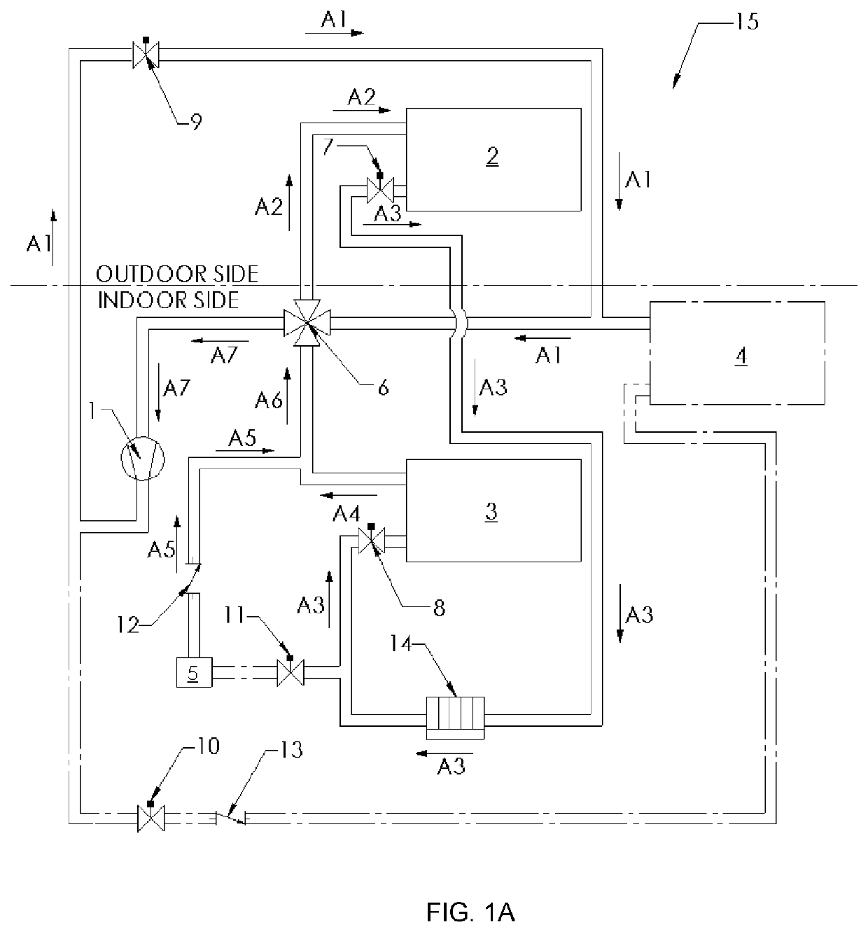
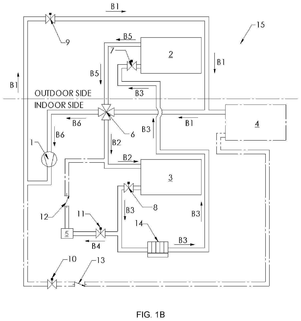
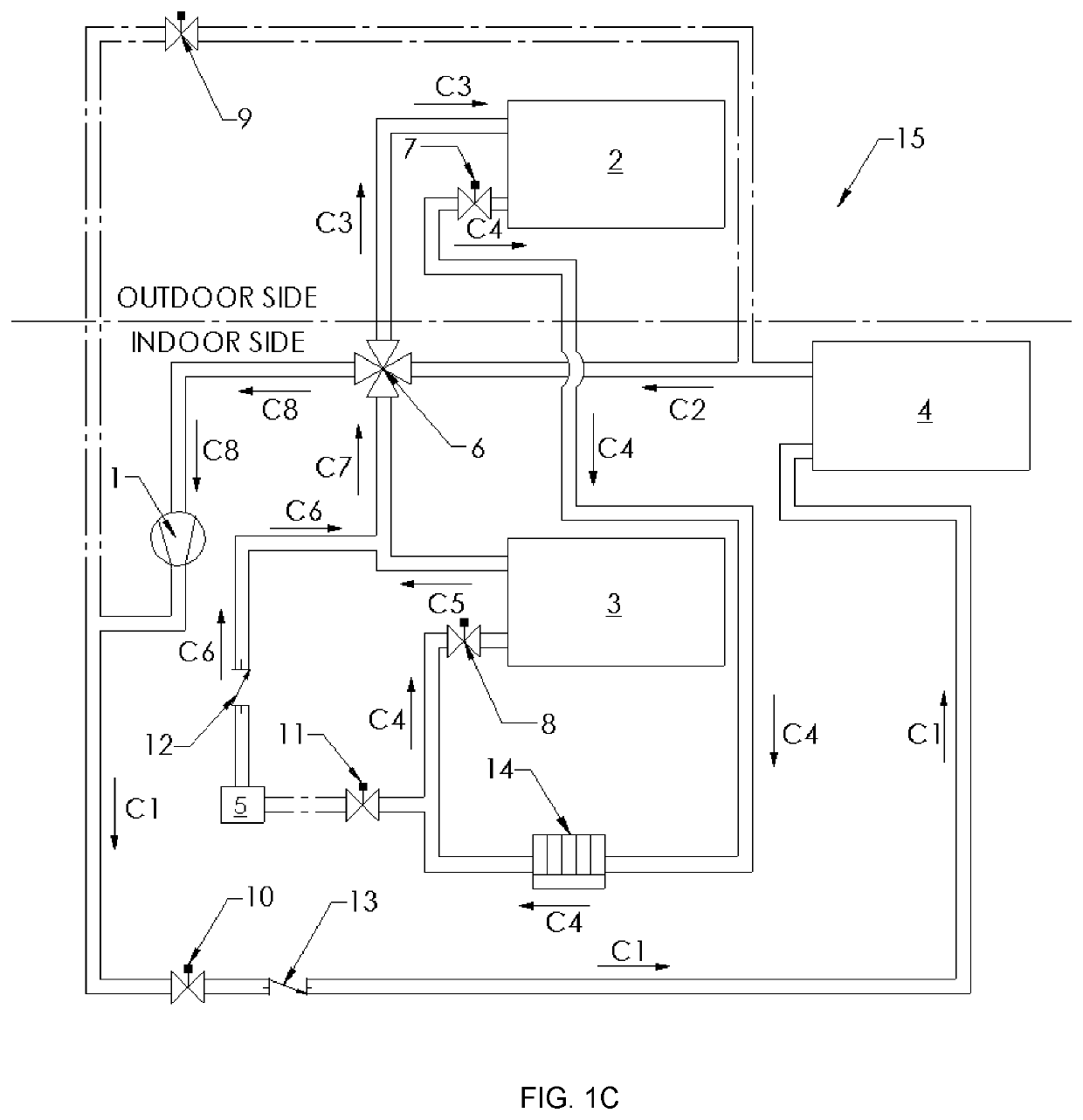
[0076]With reference to the drawings (FIGS. 1A,1B, and 1C) a packaged heat pump (air conditioning) system (unit) (15) comprises: at least one compressor (1), at least one outdoor heat exchanger (2), at least one indoor heat exchanger (3), at least one hot gas heat exchanger (4), at least one reversing valve (6), refrigerant charge control reservoir (5), expansion valves (7, 8), flow control (e.g. solenoid) valves (9, 10 and 11), check valves (12, 13) and filter drier (14). The indoor heat exchanger (3) along with the hot gas coil (4) forms part of the indoor section of the unit and is used to heat / cool and condition the building space.

[0077]FIG. 1A depicts the refrigerant cycle flow for the ASHP unit (15) operating in a cooling mode. The conduits depicted in hashed lines denote conduits through which refrigerant does not flow; although, refrigerant might be contained therein. The compressor (1) compresses and discharges the refrigerant in the form of high pressure vapor typically in...


PUM


Abstract

An air source or water sourced packaged self-contained heat pump unit comprises indoor and outdoor sections. Heat exchangers present in these sections transfer heat between the indoor building space and the outdoor ambient. The heat exchangers are connected to form a closed loop and a compressor present in the loop pressurizes the refrigerant. A refrigerant charge control system present controls the charge of refrigerant in the main refrigerant system during heating and cooling modes. A hot-gas heat exchanger is added to the indoor section of the unit downstream of the indoor heat exchanger with respect to the airflow. Valves are used to bypass the flow of refrigerant from the compressor to the hot-gas heat exchanger during regular heating and cooling modes. In the hot-gas reheat mode, the compressed refrigerant is first directed to the hot gas heat exchanger which reheats the air to decrease the relative humidity. The charge control system is active during the hot gas reheat cycle to control the charge of refrigerant in the system.

Description

CROSS-REFERENCE TO EARLIER-FILED APPLICATION[0001]This application claims the benefit of application No. 62 / 699,052 filed Jul. 17, 2018, the entire disclosure of which is hereby incorporated by reference.FIELD OF THE INVENTION[0002]This invention pertains to packaged air source heat pump units and packaged water source heat pump units. In particular, the invention concerns a refrigerant charge control system that controls the amount of refrigerant being used in the main refrigerant loop during a cooling cycle and / or a heating cycle in the units, whereby the amount of refrigerant in the main refrigerant loop is different when comparing the cooling cycle and heating cycle modes. The invention also concerns refrigerant systems that provide reheat function during cooling mode.BACKGROUND OF THE INVENTION[0003]A packaged heat pump unit typically comprises the following major components: compressor, reversing valve, and at least two heat exchangers with expansion valves. One of the heat ex...

Claims


Application Information

Patent Timeline
Patent Type & Authority Applications(United States)
IPC IPC(8): F24F3/153F25B30/02F25B41/04F25B49/02
CPCF25B41/04F25B2313/029F24F3/153F25B2600/2507F25B49/02F25B30/02F25B2313/004F25B2600/05F25B41/20F25B41/24
Inventor LEON, FELIPE
Owner UNITED ELECTRIC CO LP
Learn More