
Circuit body and battery module

Active Publication Date: 2020-01-16
YAZAKI CORP
View PDF0 Cites 4 Cited by
  • Summary
  • Abstract
  • Description
  • Claims
  • Application Information

AI Technical Summary

Benefits of technology

The patent text describes a circuit body and a battery module that can simplify the detection of voltage in a battery assembly. The circuit body is designed with overlapping parts and the conductors are arranged in the potential order of the battery assembly. This eliminates the need for a circuit to rearranged the voltage detection lines and simplifies the overall circuit. The battery module has terminals that are arranged in the voltage order of the battery assembly, making it easier to connect to external devices that monitor the battery's voltage and adjust charging. Overall, this invention allows for simpler and more efficient detection of battery voltage.

Problems solved by technology

Therefore, voltage detection lines extending from the bus bars to a connector are not arranged in the voltage order, which causes a circuit to be complicated by providing a circuit or the like which rearranges the voltage detection lines in the voltage order on an ECU side.

Method used


Image

  • Circuit body and battery module
  • Circuit body and battery module
  • Circuit body and battery module

Examples


first embodiment

[0038]First, a battery module according to a first embodiment will be described.

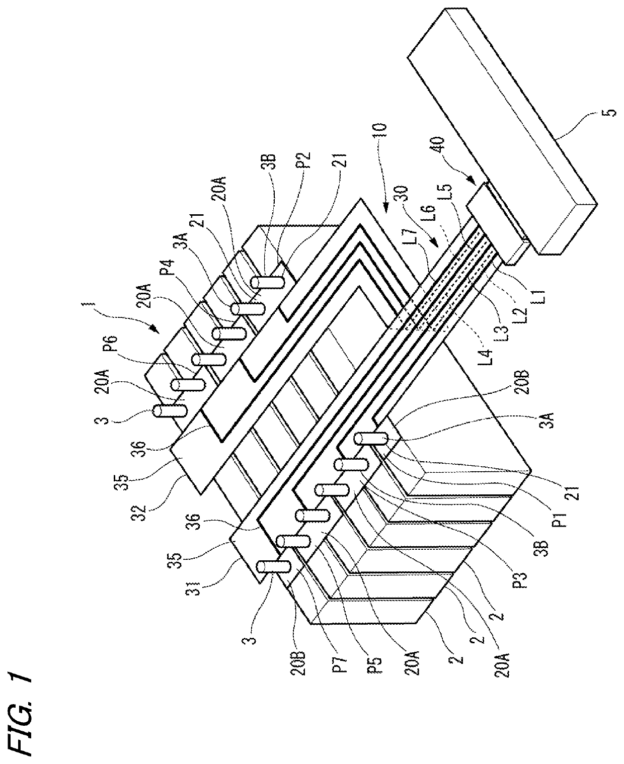
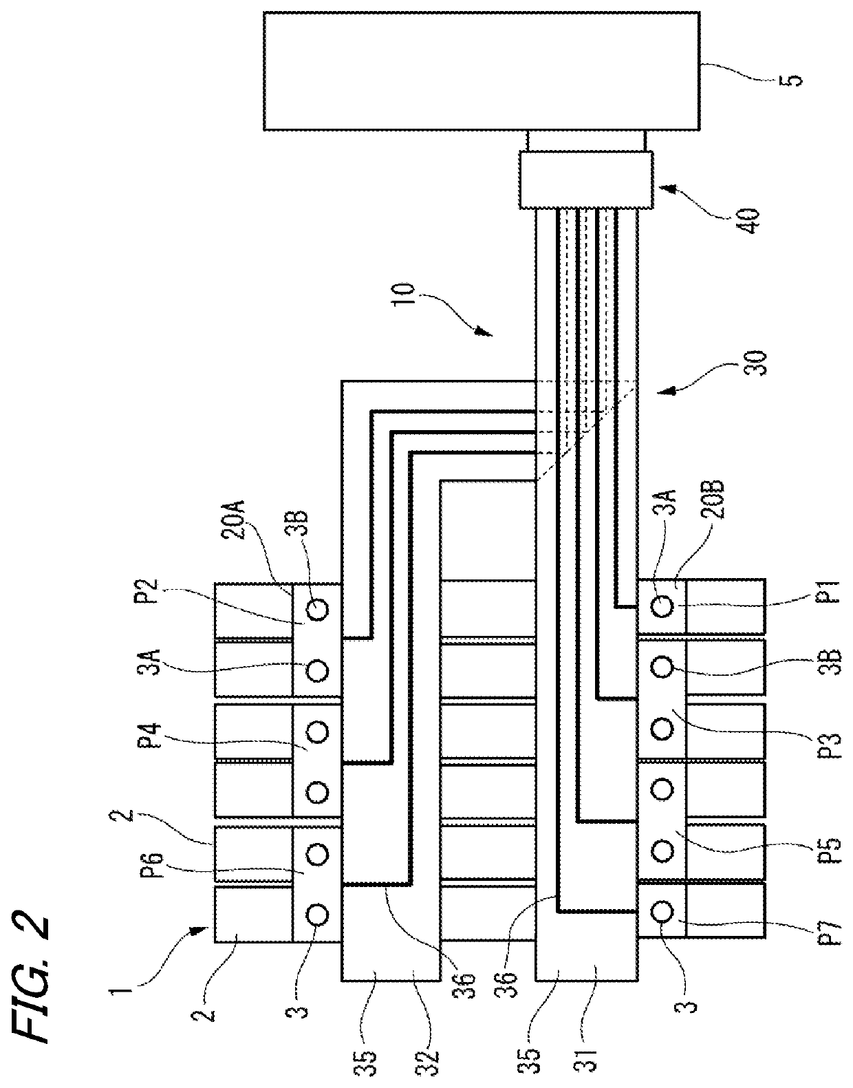
[0039]FIG. 1 is a perspective view of a battery assembly in which the battery module according to the first embodiment is assembled. FIG. 2 is a plan view of the battery assembly in which the battery module according to the first embodiment is assembled.

[0040]As illustrated in FIGS. 1 and 2, a battery module 10 according to the first embodiment is assembled to a battery assembly 1. The battery assembly 1 is used, for example, as a power source of an electric car, a hybrid car, or the like. The battery assembly 1 is constituted of battery cells 2 composed of a plurality of secondary batteries.

[0041]The battery cells 2 are stacked on one another to constitute a battery assembly 1. Each battery cell 2 has a pair of electrodes 3 at the top. One of the pair of electrodes 3 is a positive electrode 3A and the other is a negative electrode 3B. The positive electrode 3A and the negative electrode 3B are disposed ...

second embodiment

[0064]Next, a battery module according to a second embodiment will be described.

[0065]The same components as those of the first embodiment are given the same reference numerals and letters and the description thereof is omitted.

[0066]FIG. 6 is a perspective view of a battery assembly in which a battery module according to the second embodiment is assembled. FIG. 7 is a plan view of a circuit body and a connector of the battery module.

[0067]As illustrated in FIGS. 6 and 7, in a battery module 10A according to the second embodiment, the circuit body 30 is formed of a single substrate 33. The substrate 33 is a flexible printed circuit (FPC) having a base 35 and a conductor 36.

[0068]The substrate 33 has a battery wiring portion 33a, a connection portion 33b, and a connector connection portion 33c. The battery wiring portion 33a and the connection portion 33b are formed to have substantially the same width and the connector connection portion 33c is formed to be narrower than the battery...


PUM


Abstract

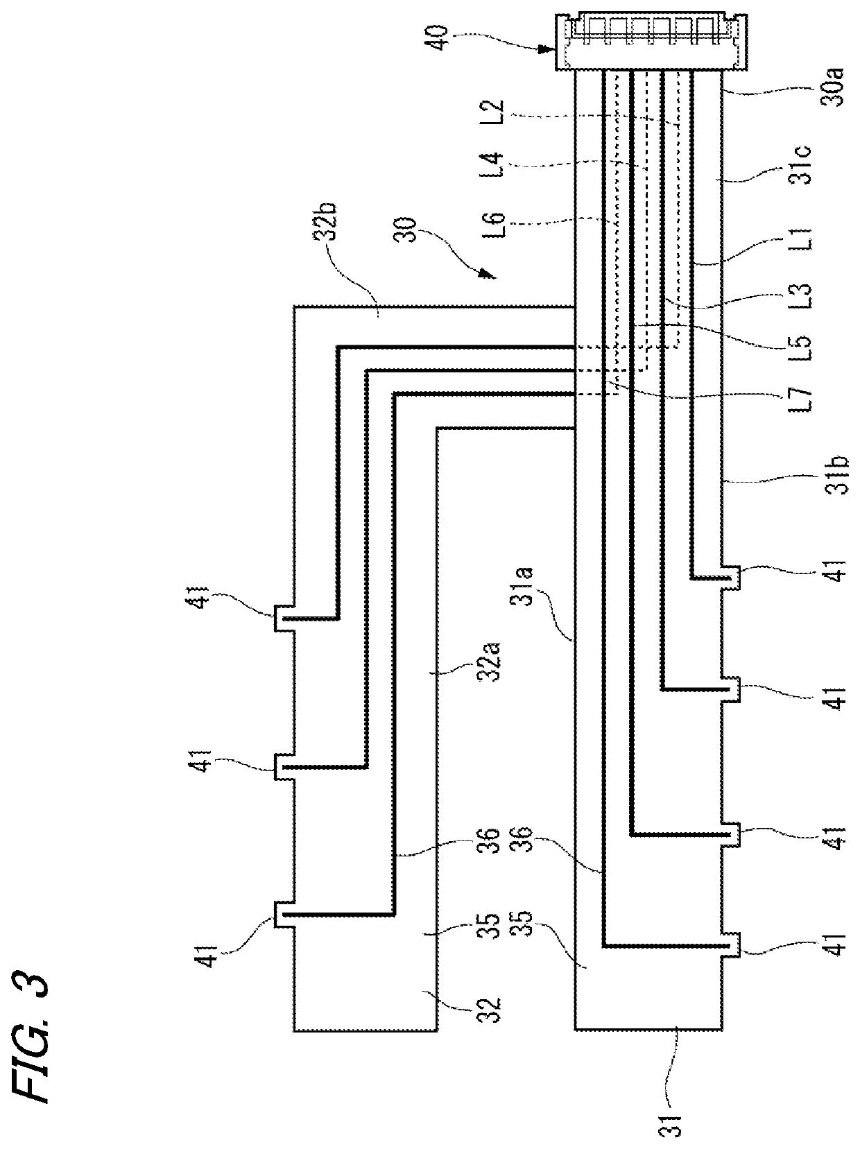
A circuit body includes: a plurality of conductors, and first and second substrates, wherein the first and second substrates include a battery wiring portion which is routed along each row of an electrodes and one ends of the conductors are respectively connected to bus bars, and a connector connection portion where the other ends of the plurality of conductors are connected to a connector, and parts of the first substrate and the second substrate are overlapped in the connector connection portion, so an arrangement order of the other ends of the conductors corresponds to the potential order of the bus bars.

Description

CROSS REFERENCE TO RELATED APPLICATIONS[0001]This application is based on and claims priority from Japanese patent application No. 2018-133502 filed on Jul. 13, 2018, the entire contents of which are incorporated herein by reference.BACKGROUND OF THE INVENTION1. Technical Field[0002]The present invention relates to a circuit body and a battery module.2. Background Art[0003]A battery module including a bus bar fixed to an electrode of each battery cell, a voltage detection line extending from the bus bar, and a connector for connecting the voltage detection line to an ECU is attached to a battery mounted in a hybrid car or an electric car. The ECU monitors the voltage of each battery cell detected through the voltage detection line of the battery module and adjusts the charge amount of the battery cell and the like. In those battery modules, there is one using a printed circuit body having a voltage detection line made of a conductor pattern in order to improve complicated wiring wor...

Claims


Application Information

Patent Timeline
IPC IPC(8): H01M2/20H05K1/11H01M10/48H01M10/42H05K1/02H05K3/36H01M2/10H01M50/209H01M50/284H01M50/298H01M50/50H01M50/519
CPCH05K1/118H05K1/028H01M2/1077H01M10/482H05K3/361H01M2/206H01M10/425H01M2220/20H01M50/50H01M50/284H01M50/298H01M50/209H01M50/519H01R11/288H01M2010/4271Y02E60/10H01M50/569
Inventor MAKINO, KIMITOSHI
Owner YAZAKI CORP
Learn More