
Arrangement for projections onto the exterior surf ace of an aircraft

a projection and aircraft technology, applied in the direction of projectors, cameras, advertising, etc., can solve the problems of increased weight or structural problems, inability to achieve the success of autogyros in commercial aviation, and inability to meet the needs of aircraft traffic, so as to improve the safety of air traffic, the effect of efficient projection and improved visibility

Inactive Publication Date: 2020-01-16
SCHEIDLER BENJAMIN
View PDF3 Cites 5 Cited by
  • Summary
  • Abstract
  • Description
  • Claims
  • Application Information

AI Technical Summary

Benefits of technology

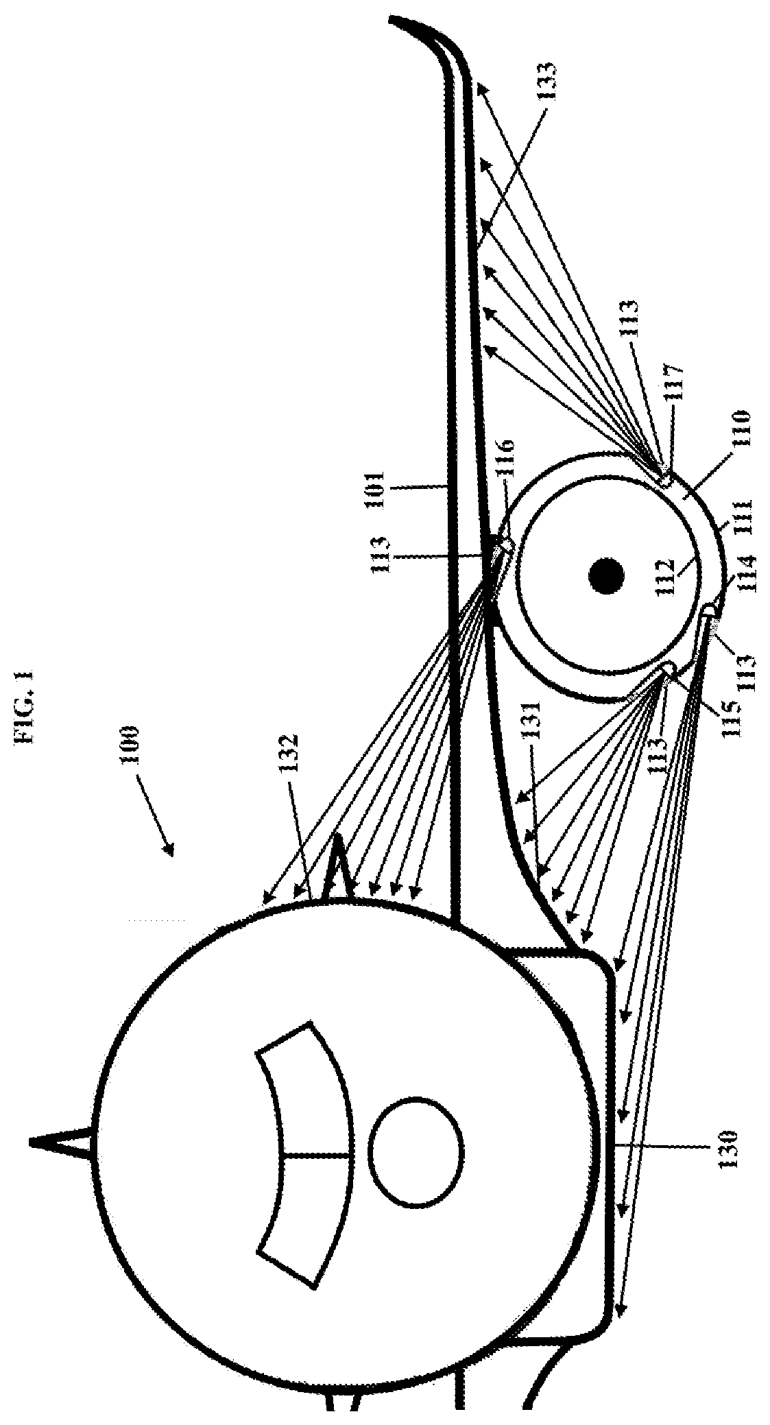
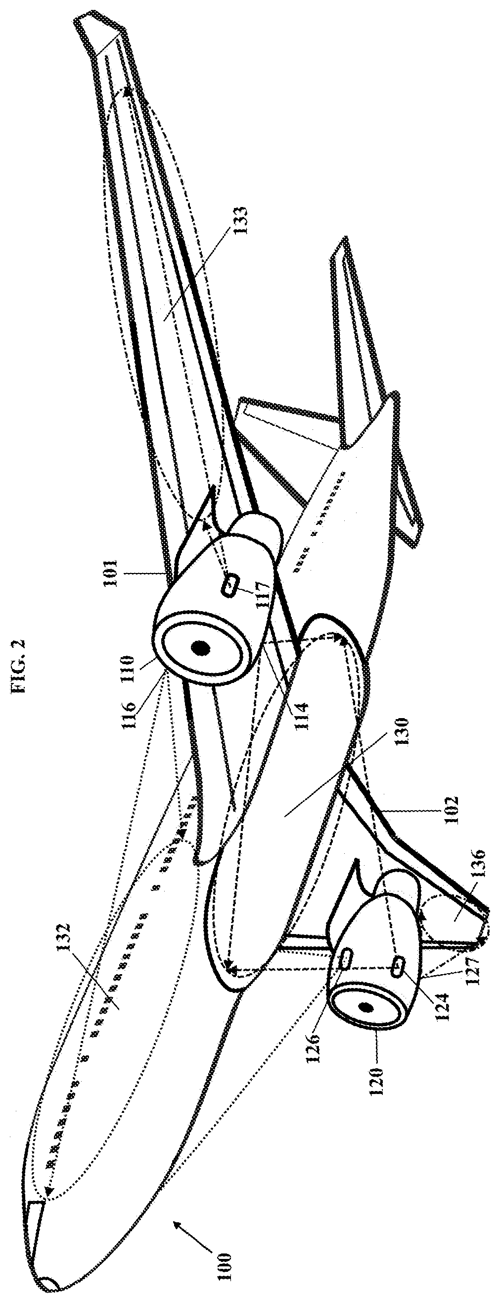
The invention is a system that can efficiently project onto the underbelly, sides, and wings of an aircraft without adding any protruding structures that affect aerodynamics or create stability issues. The system can also be retrofitted to existing aircraft. The stated goal is to improve security by using lights to make the aircraft more easily visible in the air and on the ground. The invention allows for the projection of simple signs or images onto the aircraft's skin using projectors that are strategically placed and can be programmed to change the illuminated area based on the viewing angle of observers. This creates a dynamic and interesting effect.

Problems solved by technology

Also autogyros had not been successful in commercial aviation.
Other approaches, such as the application of lighting panels or displays on aircraft exterior surfaces as proposed in U.S. Pat. Nos. 8,933,819B1, 9,324,248B2 and US20160042675A1 have their limitations firstly in the mounting on three-dimensional curved surfaces but also in terms of durability of the systems under onerous environmental stress from solar radiation and weathering especially at high altitudes.
Moreover, their attachment to aerodynamically highly stressed parts or onto the heavily loaded outer skin of the cabin will lead to constructions with increased weight or structural problems.
This is difficult to implement because both parts are aerodynamically highly stressed structures.
Also the installation into the skin of the pressurized cabin needs cut-outs which weakens the strength of the skin.
Because of these problems the installation needs a lot of effort and retrofitting is hardly possible.
In this case, the advantage of the projection does not outweigh the disturbances in aerodynamics and again the potential stability problems with the attachment to the skin of the pressurized cabin.
Application of the necessary means for extending and retracting of such projection systems would also be intricate.

Method used


Image

  • Arrangement for projections onto the exterior surf ace of an aircraft
  • Arrangement for projections onto the exterior surf ace of an aircraft

Examples


Embodiment Construction

[0017]According to this invention, the term “projector” means both a light projector for the illumination of existing images on the aircraft fuselage and also a projector for the projection of pictures or videos onto the exterior surface of an aircraft.

[0018]The light projector can consist of any type of light source that emits a beam of light regardless of the colour of the light. LEDs are a suitable light source as they have a compact design, low energy consumption and low heat development. The illuminated image can be a logo, a brand name, an advertisement or any other painted or attached sign on the aircraft exterior surface.

[0019]The projector for the projection of pictures or videos can be a laser, a DLP, a LED, a LCD or any other type of projector which can project picture or videos.

[0020]FIG. 1 shows a frontal view of a commercial aircraft 100 with its left wing 101 and left engine 110.

[0021]Due to reasons of noise reduction and air guidance to the engine core there is suffi...


PUM


Abstract

The attachment of a projector under the cowling of a turbofan engine of a modern commercial aircraft allows the illumination of the underside and of the sides of the aircraft fuselage and also of the underside of the wings. With this arrangement it is also possible to project images or even videos onto these areas.

Description

TECHNICAL FIELD[0001]The present disclosure relates to exterior aircraft lighting respectively projection. In particular, it relates to an arrangement of projectors for a better visibility of an aircraft and also for advertisement purpose.BACKGROUND INFORMATION[0002]There are several exterior light installations on aircraft. The landing, runway turnoff, taxi and wing lights are used for the illumination of the environment and parts of the aircraft for a better visibility for the crew. The strobe, navigation, anticollision and logo lights have a signalling function and increase the visibility of the aircraft for others. An increased visibility of an aircraft has safety benefits for air traffic in the vicinity because the aircraft can be detected visually more easily and quickly by other pilots. This is a safety benefit particularly around busy airports because approaching and departing, consequently ascending and descending, traffic often intersects. With projection lighting onto the...

Claims


Application Information

Patent Timeline
Patent Type & Authority Applications(United States)
IPC IPC(8): B64D47/02G09F19/00G09F13/02
CPCG09F13/02B64D2203/00B64D47/02G09F19/00G09F21/10G09F19/18G03B29/00
Inventor SCHEIDLER, BENJAMIN
Owner SCHEIDLER BENJAMIN
Learn More