
Fuel cell separator member and fuel cell stack

a separator and fuel cell technology, applied in the direction of collectors/separators, fuel cells, motive system fuel cells, etc., can solve problems such as cost rise, and achieve the effect of simple and economical configuration

Inactive Publication Date: 2020-01-09
HONDA MOTOR CO LTD
View PDF0 Cites 1 Cited by
  • Summary
  • Abstract
  • Description
  • Claims
  • Application Information

AI Technical Summary

Benefits of technology

The present invention aims to provide a separator member and fuel cell stack with a simple and economical configuration that can make the surface pressure applied to the bead seals around a coolant passage uniform. By not forming notched portions in the first and second bead seals, the load bearing characteristics of these seals are not deteriorated, resulting in a uniform surface pressure. This configuration ensures a more robust and reliable performance of the fuel cell.

Problems solved by technology

For such seal members, elastic rubber seals made of fluorine-based rubber or silicone or the like are used, which leads to a rise in costs.

Method used


Image

  • Fuel cell separator member and fuel cell stack
  • Fuel cell separator member and fuel cell stack
  • Fuel cell separator member and fuel cell stack

Examples


Embodiment Construction

[0025]Preferred embodiments of a fuel cell separator member and a fuel cell stack according to the present invention will be presented and described below with reference to the accompanying drawings.

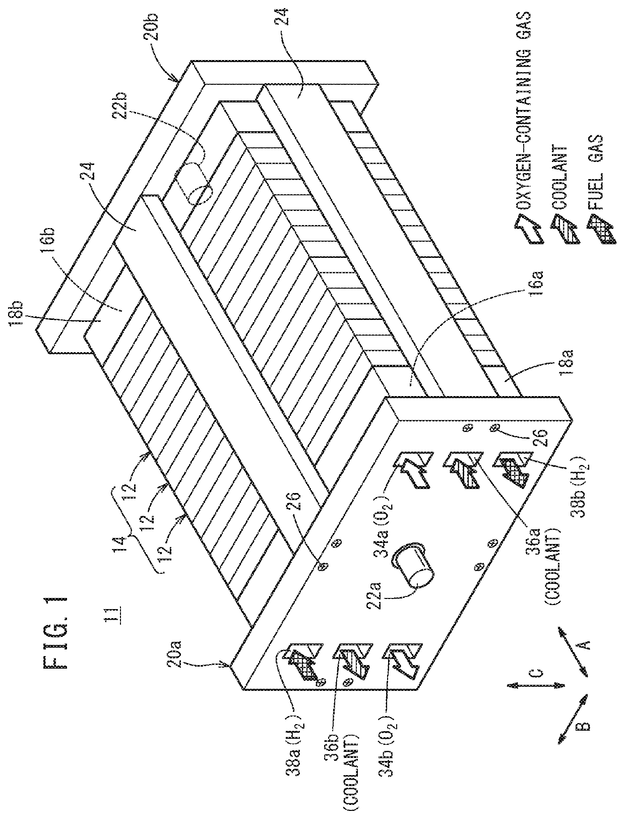
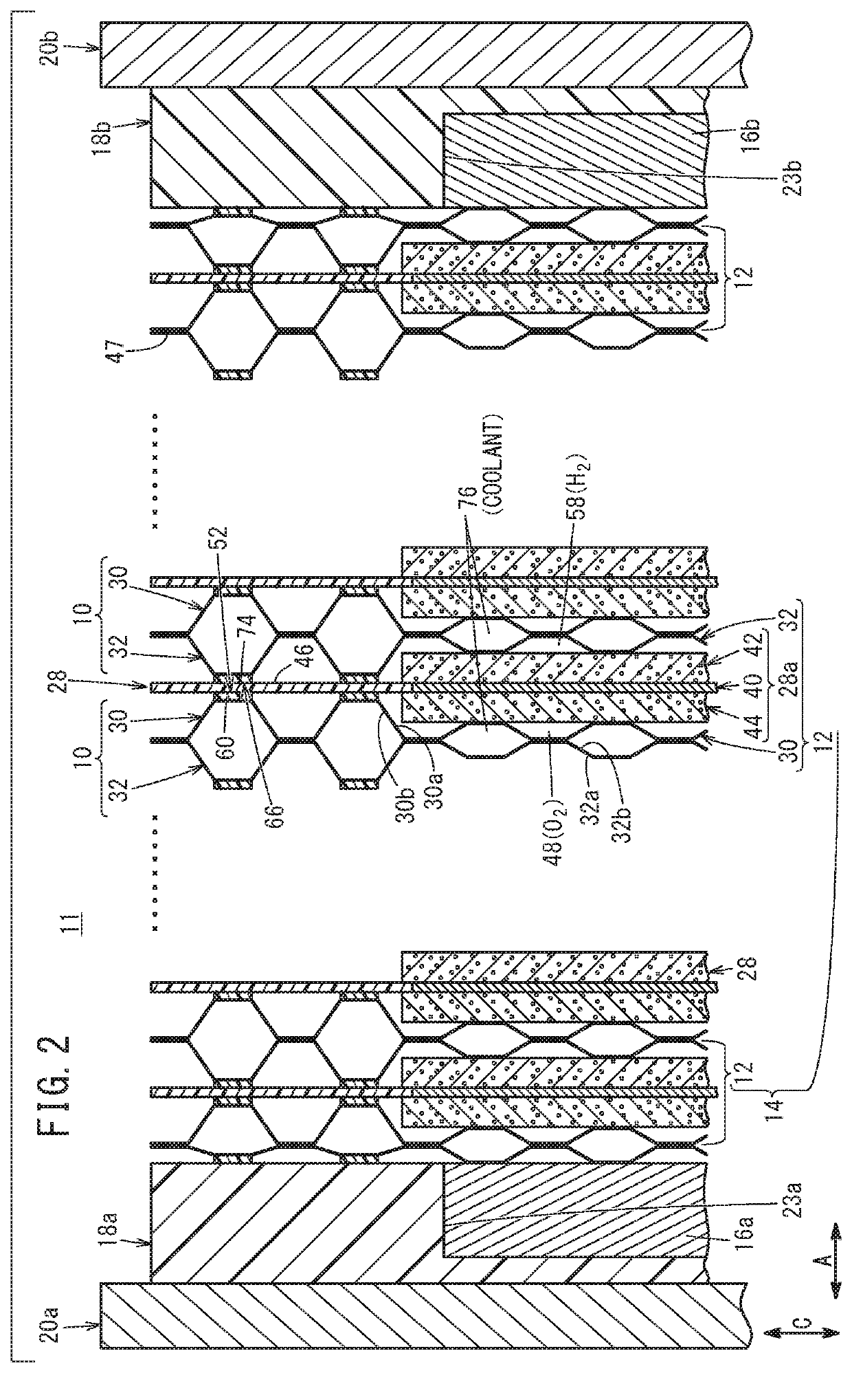
[0026]As shown in FIGS. 1 and 2, a fuel cell stack 11 according to a first embodiment of the present invention comprises a stacked body 14 in which a plurality of power generation cells 12 are stacked in a horizontal direction (the direction of the arrow A). The fuel cell stack 11, for example, is mounted in a fuel cell vehicle such as a fuel cell electric automobile (not shown).

[0027]A terminal plate 16a, an insulator 18a, and an end plate 20a are arranged in this order sequentially toward the outside on one end in the stacking direction (the direction of the arrow A) of the stacked body 14. A terminal plate 16b, an insulator 18b, and an end plate 20b are arranged in this order sequentially toward the outside on another end in the stacking direction of the stacked body 14.
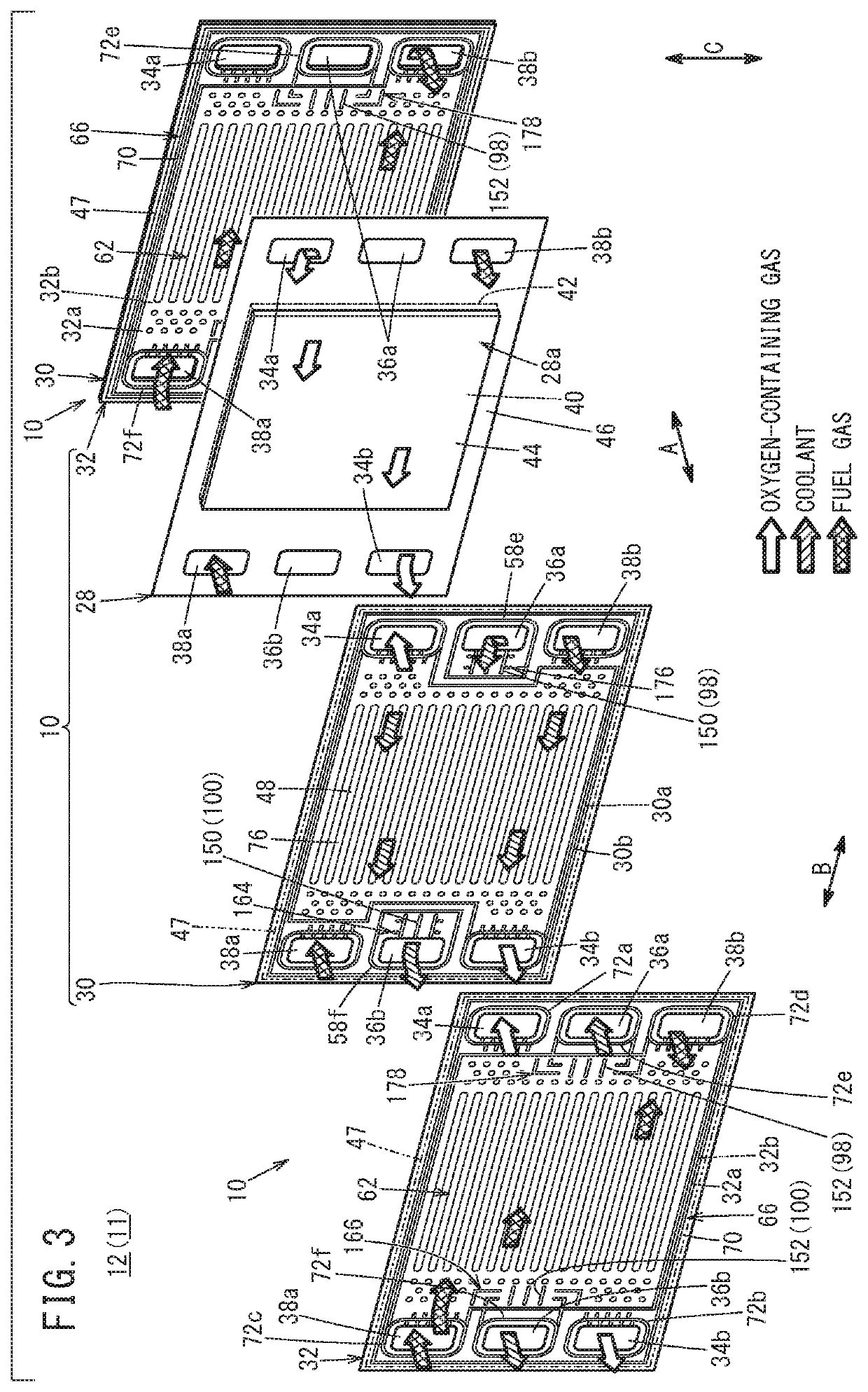
[0028]As shown...


PUM

PropertyMeasurementUnit
thicknessaaaaaaaaaa
compressiveaaaaaaaaaa
heightaaaaaaaaaa

Abstract

In a coolant inlet bridge section of a fuel cell separator member constituting a component of a fuel cell stack, as viewed in plan from a separator thickness direction, a first projection forming a first communication passage that communicates with a coolant supply passage extends in a manner so as to intersect with a second communication passage bead section, and a second projection forming a second communication passage configured to enable mutual communication between the first communication passage and a coolant flow field extends in a manner so as to intersect with a first communication passage bead section.

Description

CROSS-REFERENCE TO RELATED APPLICATION[0001]This application is based upon and claims the benefit of priority from Japanese Patent Application No. 2018-128661 filed on Jul. 6, 2018, the contents of which are incorporated herein by reference.BACKGROUND OF THE INVENTIONField of the Invention[0002]The present invention relates to a fuel cell separator member and a fuel cell stack, in which a coolant flow field is formed between a first separator and a second separator that are stacked on each other.Description of the Related Art[0003]For example, a solid polymer electrolyte fuel cell is equipped with a membrane electrode assembly (MEA) in which an anode is disposed on one side surface and a cathode is disposed on another side surface, respectively, of an electrolyte membrane made up from a polymer ion exchange membrane. In the fuel cell, the membrane electrode assembly is sandwiched between separators (bipolar plates) in order to form a power generation cell (unit cell). A fuel cell st...

Claims


Application Information

Patent Timeline
Patent Type & Authority Applications(United States)
IPC IPC(8): H01M8/0276H01M8/0258H01M8/0267H01M8/2475H01M8/0273
CPCH01M2250/20H01M8/0267H01M8/2475H01M8/0258H01M8/0273H01M8/0276H01M8/0206H01M8/241H01M8/0254H01M8/2483H01M8/248Y02E60/50
Inventor GOTO, SHUHEITOMANA, YUGIGA, AKIHITO
Owner HONDA MOTOR CO LTD
Learn More