Adaptive retro-reflector (AR)

Active Publication Date: 2020-01-09
UNITED STATES OF AMERICA
View PDF0 Cites 0 Cited by
  • Summary
  • Abstract
  • Description
  • Claims
  • Application Information

AI Technical Summary

Benefits of technology

The invention improves the performance of optical communication links by adjusting the divergence of an optical beam. This helps to increase the distance between optical devices or maintain higher performance over longer distances. The invention allows for quick control of beam divergence and can maintain a desired position without consuming additional power. This results in better performance in dynamic systems where the distance between devices can vary.

Problems solved by technology

A large percentage of the energy in a monostatic-configured passive retro-reflector is wasted due to the divergence of the beam and turbulence effects.
A passive retro-reflector having a conventional bi-static or off-axis configuration either requires a second transmitter for the return signal, or increases divergence to increase footprint of returning beam, which leads to energy losses.
Such energy losses limit performance and propagation distances of a passive retro-reflector having a bi-static or off-axis configuration.
However, this lens limits the performance of the system because there is always power introduced in the system due to the lens and the fixed prescription of such lens.
If such a conventional configuration sits on one or more movable platforms, the performance of the configuration is also negatively impacted by platform dynamics, e.g., the platform moving or by moving from one platform to another.
For example, the performance of a conventional passive retroreflector or a conventional lens-passive-retroreflector combination is limited or degraded by the constant change in distance between platforms and / or other effects as mentioned above.

Method used


Image

  • Adaptive retro-reflector (AR)
  • Adaptive retro-reflector (AR)
  • Adaptive retro-reflector (AR)

Examples


Embodiment Construction

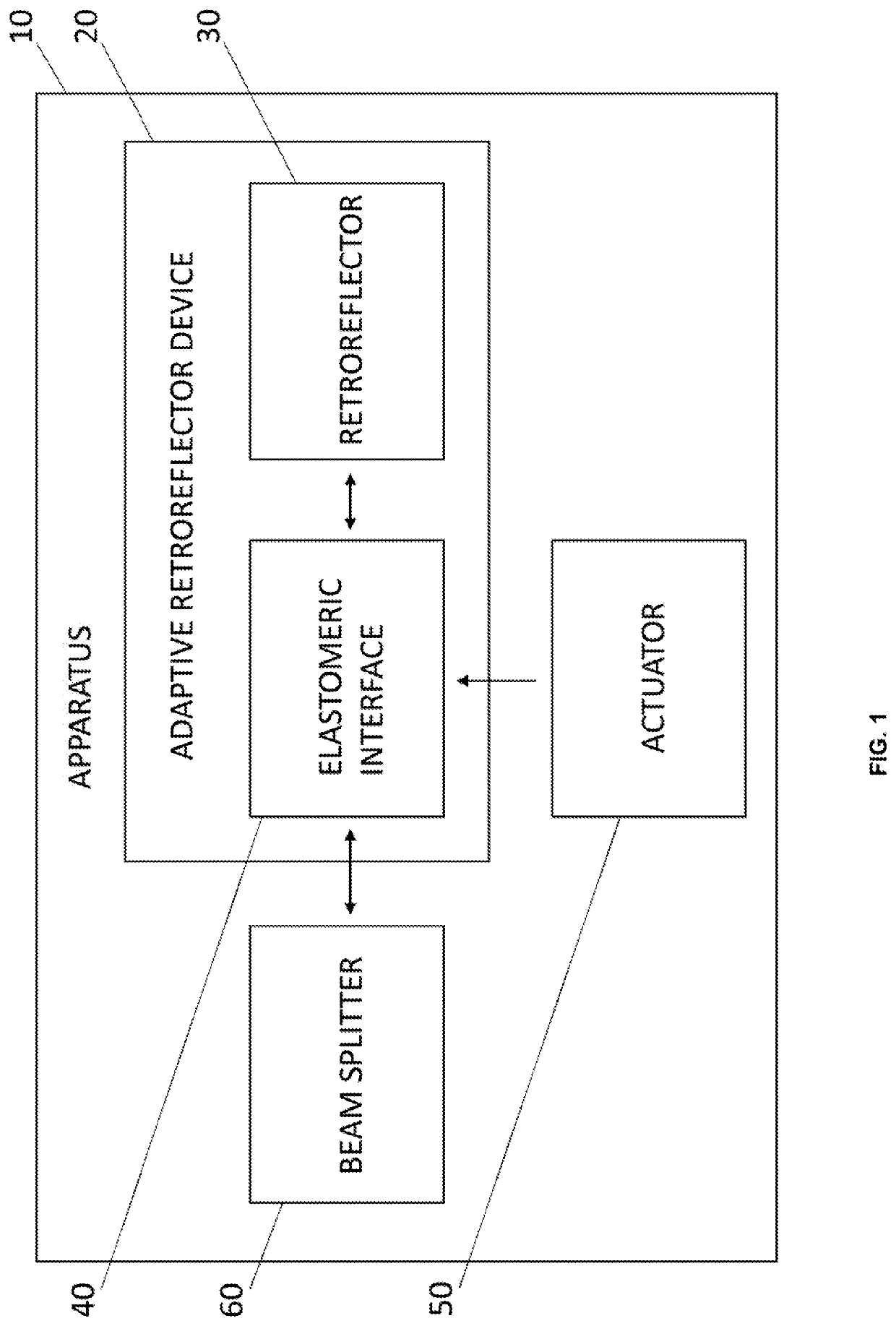
[0019]An apparatus 10 according to an embodiment of the invention is described as follows with reference by way of illustration to FIG. 1. The apparatus 10 includes a refractive active element, namely, an adaptive retro-reflector device 20. The adaptive retro-reflector device 20 includes a standard retro-reflector 30. In operation, the retro-reflector 30 receives an incident optical signal (i.e., an incident beam of electromagnetic radiation) and outputs a returned optical signal (i.e., an outgoing beam of electromagnetic radiation). The returned optical signal includes, or exhibits, a change in divergence. For the purpose of this patent application, “divergence” of an optical signal is defined as how much, in terms of an angular measurement, the beam diameter changes with increasing distance. That is, divergence refers to how fast a light beam expands far from its beam waist. For longer distances, light beams exhibit divergence due to diffraction, atmospheric effects (e.g., thermal...


PUM


Abstract

An apparatus includes an adaptive retro-reflector device. The adaptive retro-reflector device includes a standard retro-reflector. In operation, the retro-reflector receives an incident optical signal and outputs a returned optical signal. The returned optical signal exhibits a divergence. The adaptive retro-reflector device includes an elastomeric interface. The elastomeric interface is in optical communication with the retro-reflector such that the incident optical signal passes through the elastomeric interface to the retro-reflector and such that the returned optical signal from the retro-reflector passes through the elastomeric interface. The elastomeric interface includes an interface surface. The apparatus includes a standard actuator. The actuator in operation communicates with the elastomeric interface so as to deform the interface surface, thereby controlling the divergence. Optionally, the elastomeric interface includes a standard elastomeric membrane and a standard optically transparent optical fluid. The optically transparent optical fluid is at least partially encapsulated by the elastomeric membrane.

Description

CROSS-REFERENCE TO RELATED APPLICATIONS[0001]This application claims priority to U.S. Provisional Patent Application Ser. No. 62 / 695,310, entitled “ADAPTIVE RETRO-REFLECTOR (“AR”),” to Santiago et al., which was filed on 9 Jul. 2018 and is incorporated herein by reference.BACKGROUND OF THE INVENTIONField of the Invention[0002]This invention relates in general to an optical retro-reflector, and in particular to an adaptive optical retro-reflector.Description of the Related Art[0003]Retro-reflectors are passive devices that return an incident optical beam through the same propagation path. Conventional passive retro-reflectors can be implemented in different systems configurations. For example, in a conventional monostatic configuration, a receiver (“Rx”) and a transmitter (“Tx”) are collocated. A large percentage of the energy in a monostatic-configured passive retro-reflector is wasted due to the divergence of the beam and turbulence effects. Other examples include a bi-static confi...

Claims


Application Information

Patent Timeline
IPC IPC(8): G02B26/00G02B5/122
CPCG02B26/004G02B5/122G02B27/0025
Inventor SANTIAGO, FREDDIEFONT, CARLOS
Owner UNITED STATES OF AMERICA
Why Eureka
Try Eureka