Configuring a communication channel between a base station and a user equipment

a communication channel and user equipment technology, applied in the field of cellular networks, can solve the problems of inability to prioritize, inability to provide sufficient over provisioning in large areas of the network, and inability to distribute huge amounts of user data over the backhaul with ultra-short delay, so as to achieve the effect of relatively quick information exchang

Active Publication Date: 2015-01-08
NOKIA SOLUTIONS & NETWORKS OY
View PDF1 Cites 3 Cited by
  • Summary
  • Abstract
  • Description
  • Claims
  • Application Information

AI Technical Summary

Benefits of technology

The patent text describes a method called CoMP that improves network coverage, increases cell-edge throughput, and enhances system efficiency. The main idea behind CoMP is to allow a user equipment (UE) to receive signals from multiple cell sites and have the UE's transmission received at multiple cell sites, regardless of the system load. If the signaling transmitted from the multiple cell sites is coordinated, the downlink (DL) performance can be significantly improved. Similarly, if the scheduling is coordinated from the different cell sites, the uplink (UL) performance can also be significantly improved. The base stations may have an X2 interface for exchanging information, which provides the advantage of quickly exchanging information. However, not all user data may always arrive in time, so inter-flexible advanced coordinated processing (IFA) may be used instead of JP-CoMP.

Problems solved by technology

From an implementation point of view one main challenge for JP-CoMP is the distribution of huge amounts of user data over the backhaul with ultra short delay.
For user data, prioritization is typically not possible or somehow meaning less due to the large amount of data.
Sufficient over provisioning in larger areas of the networks is certainly quite costly.
At the same time larger delay lead to larger feedback outdating for the channel state information (CSI) degrading the performance of joint transmission significantly.

Method used


Image

  • Configuring a communication channel between a base station and a user equipment
  • Configuring a communication channel between a base station and a user equipment
  • Configuring a communication channel between a base station and a user equipment

Examples


Embodiment Construction

[0060]In the following, embodiments of the herein disclosed subject matter are illustrated with reference to the drawings and reference to aspects of current standards, such as LTE, and their further developments. However, such reference to current standards is only exemplary and should not be considered as limiting the scope of the claims.

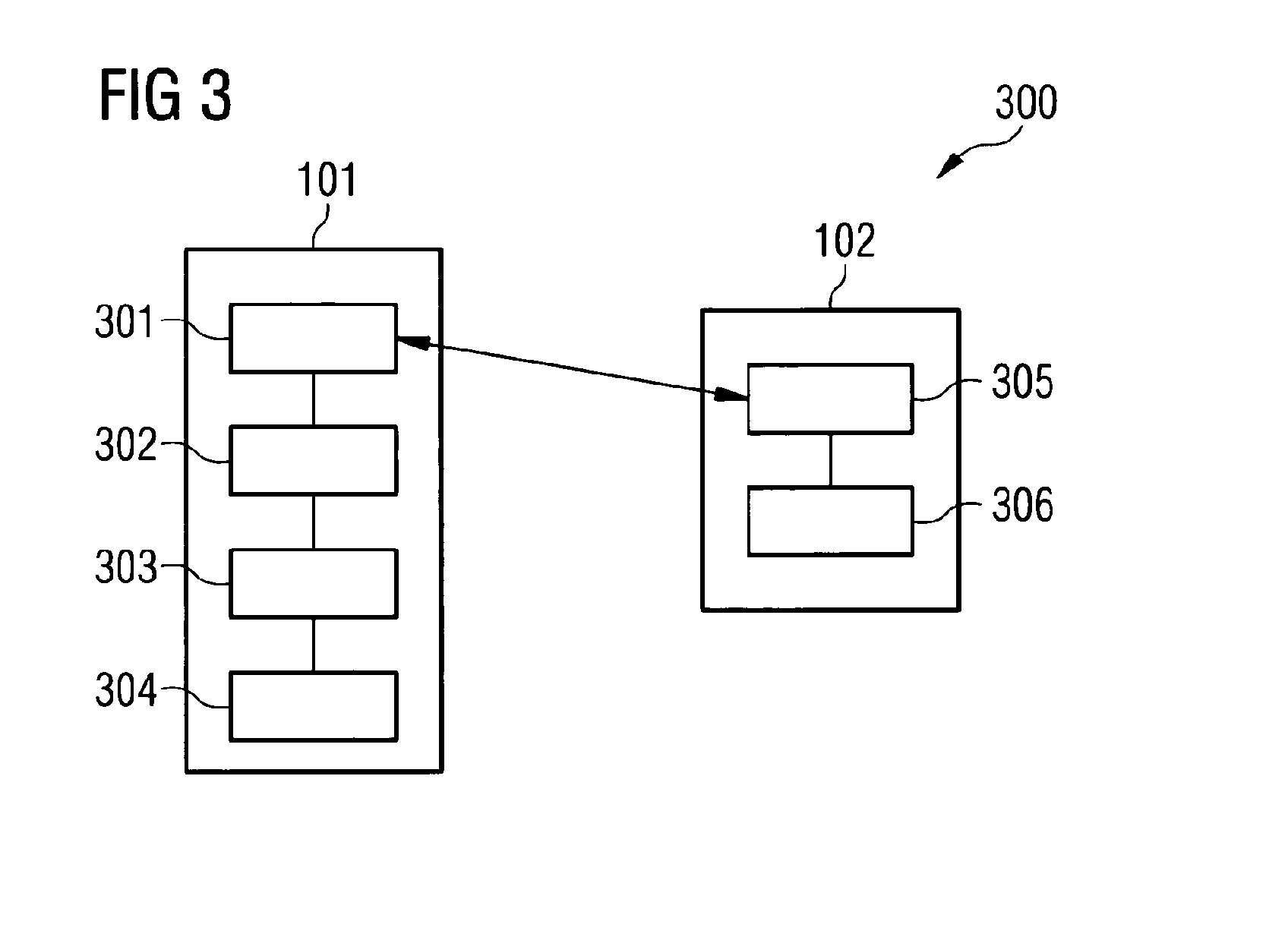
[0061]FIG. 1 shows a cellular network system 100. The cellular network system comprises a cooperation area 104. A base station 101 and a further base station 103 are assigned to the cooperation area. A user equipment 102 is served by the base station 101.

[0062]The base station 101 determines whether all user data of the user equipment 102 being required for a joint precoding coordinated multipoint transmission is received by each of the base station 101 and the at least one further base station 103. Based on this, the base station 101 selects a transmission mode. If all user data of the user equipment 102 being required for a joint precoding coord...


PUM


Abstract

A method is provided wherein a base station and at least one further base station are assigned to a cooperation area, wherein a user equipment is served by the base station. The method comprises determining, by the base station), whether all user data of the user equipment being required for a precoding coordinated multipoint transmission is received by each of the base station and the at least one further base station, selecting a transmission mode, wherein the transmission mode is based, if all user data of the user equipment being required for a precoding coordinated multipoint transmission is received by each of the base station and the at least one further base station, on precoding coordinated multipoint transmission, or else, on an interference reducing transmission, and configuring, by the base station, the communication channel between the base station and the user equipment based on the selected transmission mode.

Description

FIELD OF INVENTION[0001]The present invention relates to the field of cellular networks, especially to network systems comprising cooperation areas, and in particular to interference mitigation within such networks.ART BACKGROUND[0002]Modern wireless communication networks often are organized in a cell structure. In LTE (3GPPP Long-Term Evolution), cells may be organized in so called cooperation areas. Cooperation areas (CAs) may be defined by one or more base stations (eNodeBs, eNBs) each serving one or more cells. Within a CA, (joint) precoding coordinated multipoint (JP-CoMP) transmission may be applied for reducing interferences within the CA.[0003]For JP-CoMP, cooperation may be performed over different sites to achieve significant performance gains. For the precoding, all involved eNBs require the channel state information (CSI) as well as the user data for all cooperating users.[0004]From an implementation point of view one main challenge for JP-CoMP is the distribution of hu...

Claims


Application Information

Patent Timeline
IPC IPC(8): H04B7/02H04B15/00
CPCH04B15/00H04B7/024H04L5/001H04L5/0035H04L5/0091H04L27/2601
Inventor ZIRWAS, WOLFGANGREDANA, SIMONERAAF, BERNHARDFAERBER, MICHAEL
Owner NOKIA SOLUTIONS & NETWORKS OY
Why Eureka
Try Eureka