Device for fixing a tube within a hole in a body tissue layer

Inactive Publication Date: 2005-02-24
SCHINKEL FLEITMANN DELIA
View PDF8 Cites 67 Cited by
  • Summary
  • Abstract
  • Description
  • Claims
  • Application Information

AI Technical Summary

Benefits of technology

[0012] For installing the new device, the tube may be inserted into the hole first, and then the other limb of the L-shaped retaining element may be inserted into the hole in parallel to the tube and afterwards, when it is already at the interior of the tissue layer, be folded on the tissue layer so that the one limb of the retaining element is aligned in parallel to the tube. Next, the tube and the one limb of the retaining element aligned in parallel to the tube are fixed to each other so that the tube is fixed with regard to the hole. An additional extension of the hole in the body tissue layer is not required for using the new device to any significant extent. There is also no significant additional stress on the body tissue layer by the retaining element. At the same time, the device may be provided at low cost and it may be used with already existing smooth wall tubes like, for example, trocar tubes. An adaptation of the device to the actually used tube at least to a certain extent is sensible. A precise matching to the respective outer diameter of the tube, however, is not required.
[0013] If the other limb of the retaining element has a flat arc-shaped cross section, and if a radius of curvature of the cross section at the lower side of the other limb facing away from the inside of the tissue layer corresponds to the outer radius of the tube, the other limb may be particularly easily brought to the interior of the tissue layer next to the tube already inserted into the hole. Upon being pushed through the hole, the other limb increases the total outer diameter of the tube and the fixing device in the hole to an only insignificant extent. Particularly, if the one limb of the retaining element has a flat profile with a low wall thickness, it has to be made sure that there is no danger of breaking at the interior of the body tissue layer. The arc-shape of the cross section of the limb, however, results into a high dimensional stability, even if the retaining element is made of plastic.
[0014] If the other limb of the retaining element is contoured at its upper side facing the interior of the body tissue layer, which stops the tissue layer from slipping off, the retention of the tube in the hole can be ensured to an even higher extent.
[0019] The new device may also have two L-shaped retaining elements which are facing each other across the tube in fixing the tube. In this way, an even more secure anchoring of the tube within the tissue layer is achieved. Both L-shaped retaining elements are preferably molded bodies of plastic, which each form both limbs of one retaining element.
[0021] In another particular embodiment of the new device having two L-shaped retaining elements, both molded bodies of plastic are attached to each other by a film hinge. Thus, they are molded of plastic in a common mold. The film hinge provides a swivel axis which runs approximately in parallel to the two one limbs and thus to the direction of main extension of the tube. On the side of the tube facing away from the film hinge a latching connection is provided between the two one limbs of the two molded bodies attached to each other. This latching connection latches-in around the tube upon compressing the molded bodies, and bears the pressure force of the molded bodies on the tube; which pressure force is required for applying the static friction fixing the one limbs of the molded bodies to the tube. This embodiment of the invention is particularly well suited for quickly fixing drain tubes, and also provides for the possibility of quickly exchanging the respective drain tube.

Problems solved by technology

Further pushing the tube into the hole, which is also unwanted, is hindered by the fixing mechanism for fixing one limb of the retaining element to the tube.

Method used


Image

  • Device for fixing a tube within a hole in a body tissue layer
  • Device for fixing a tube within a hole in a body tissue layer
  • Device for fixing a tube within a hole in a body tissue layer

Examples


Embodiment Construction

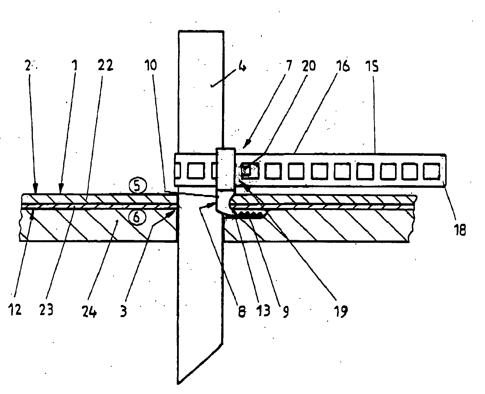
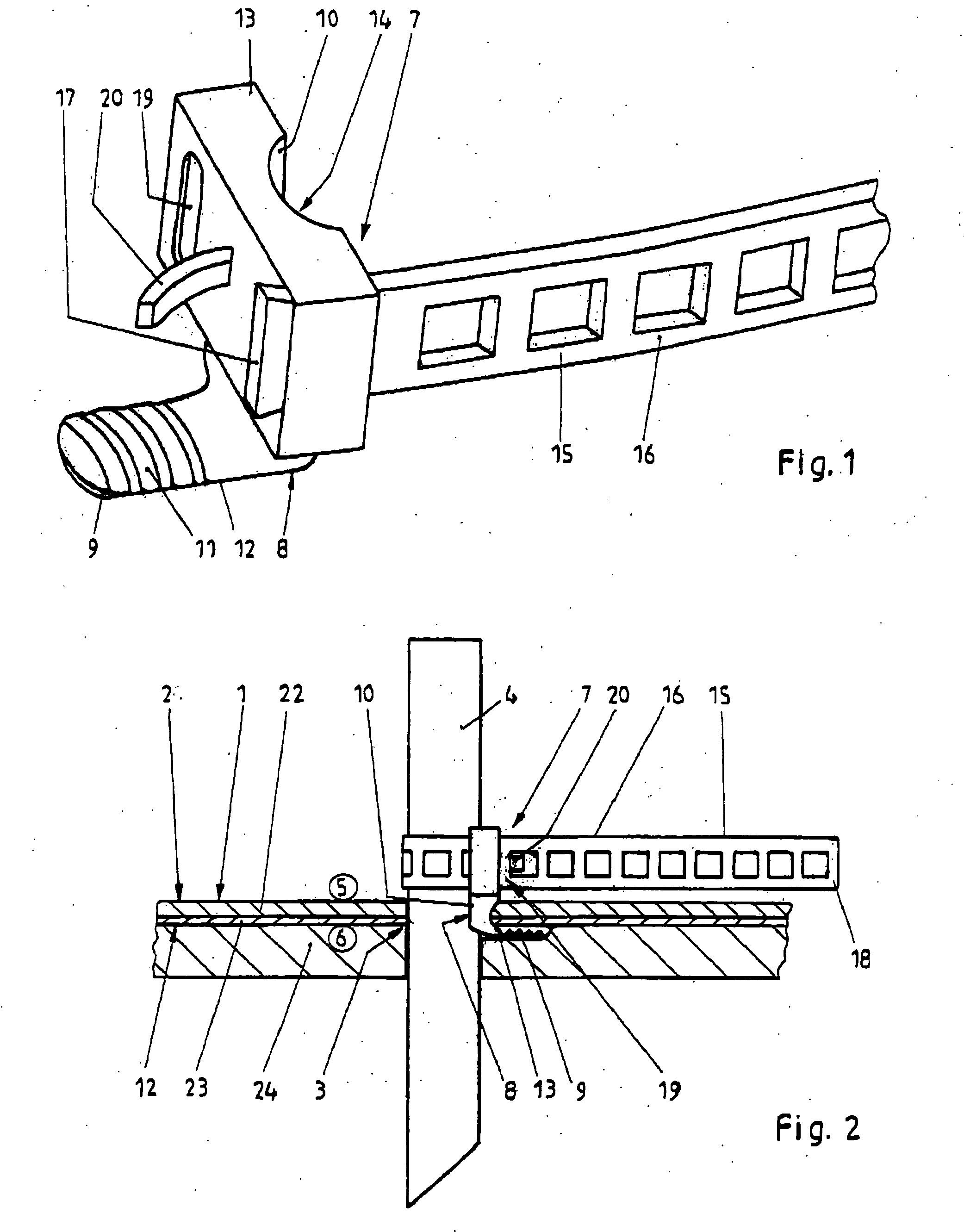
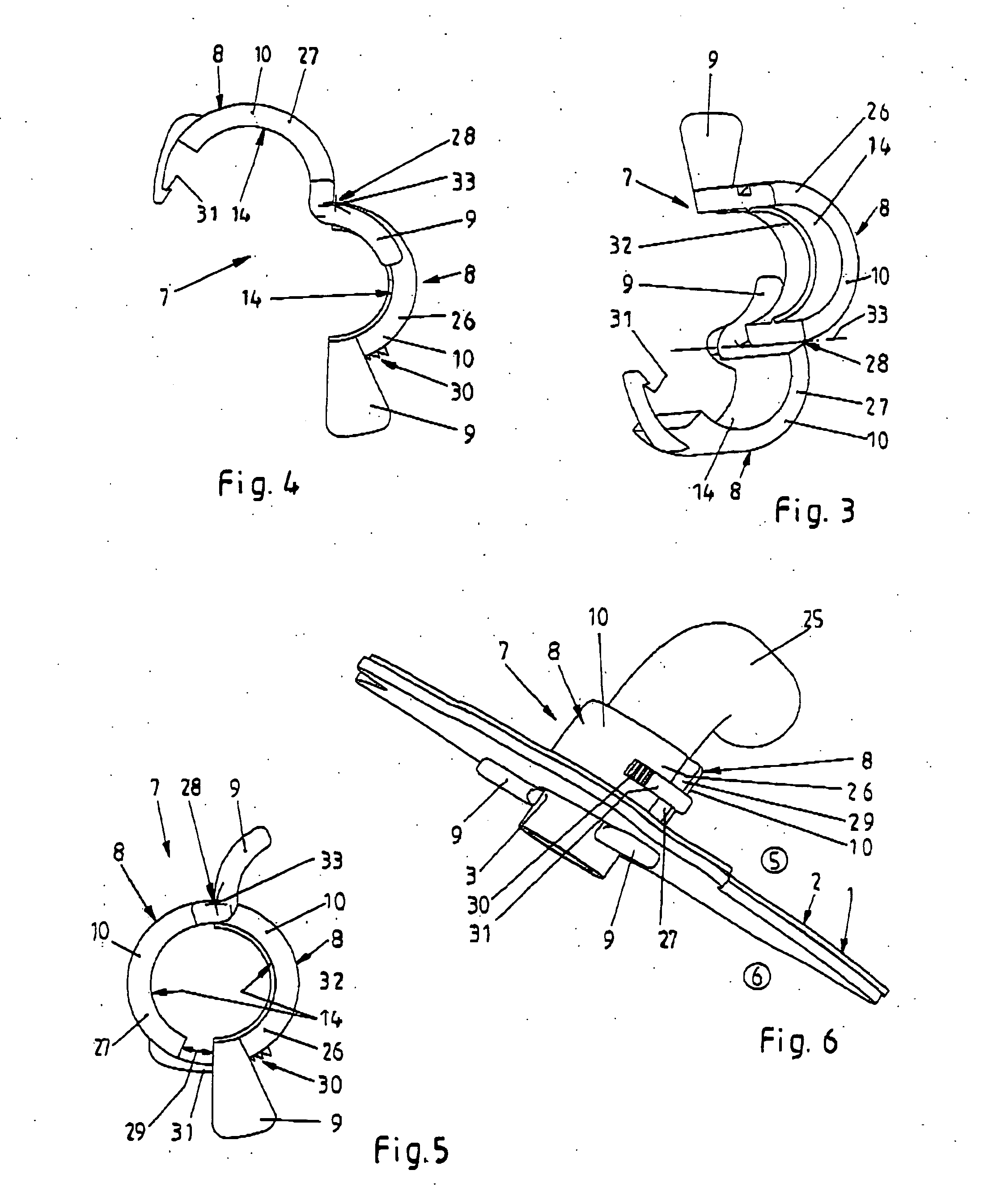
[0030] Referring now in greater detail to the drawings, FIGS. 1 and 2 illustrate a device 7 which is intended for fixing a tube, such as a trocar 4 tube shown in FIG. 2, with regard to a body tissue layer 1. The body tissue layer typically is a skin 2. The trocar tube has a smooth wall. A hole 3 is provided in the tissue layer 1, i.e. cut-in with a scalpel, through which the trocar tube 4 extends from an exterior 5 to an interior 6 of the body tissue layer 1. The device 7 includes an L-shaped retaining element 8 having two limbs 9 and 10. In the use of the device 7 according to FIG. 2, the limb 9 is arranged at the interior 6 of the tissue layer 1, and it is placed flat on the tissue layer 1 there. Particularly, it is arranged at the interior 6 of a cutis 12 consisting of an epidermis 22 and a corium 23 of the skin 2, i.e. it is still above a subcutis 24. An upper side of the limb 9 may be provided with a contour 11 as depicted in the figures to stop the tissue layer 1 from involunt...


PUM


Abstract

A device for fixing a tube having a smooth wall within a hole in a body tissue layer having an exterior and an interior comprises a L-shaped retaining element having two limbs, and a fixing mechanism for fixing one of said two limbs of said retaining element to the wall of the tube, after the other of said two limbs of the retaining element has been inserted from the exterior of the body tissue layer through the hole to the interior of the body tissue layer and placed flat on the body tissue layer at the interior of the body tissue layer.

Description

CROSS REFERENCE TO RELATED APPLICATIONS [0001] This application is a continuation in part of International Patent Application PCT / EP03 / 03164 filed Mar. 27, 2003 and claiming priority to co-pending German Patent Application No. 102 14 414.1 filed Mar. 30, 2002 both of which are entitled “Vorrichtung zur Fixierung eines Trokars, eines Schlauchs oder Katheters”.FIELD OF THE INVENTION [0002] The present invention generally relates to fixing a tube within a hole in a body tissue layer. More particular the present invention relates to a device for fixing a trocar tube, a drain tube or a catheter tube having a smooth wall within a hole in a body tissue layer having an exterior and an interior, especially in a skin or body wall. BACKGROUND OF THE INVENTION [0003] In endoscope operations, such as laparoscopy, metal or plastic tubes called trocars are inserted through the skin and the adjacent body wall into the interior of the body to provide a working channel. Through the trocar tube, the s...

Claims


Application Information

Patent Timeline
IPC IPC(8): A61B17/00A61B17/34A61M25/02
CPCA61B17/3417A61B2017/00477A61B2017/347A61B2017/348A61M2025/024A61B2017/3484A61B2017/3492A61M25/02A61B2017/3482
Inventor SCHINKEL-FLEITMANN, DELIA
Owner SCHINKEL FLEITMANN DELIA
Why Eureka
Try Eureka