A Magnetic Battery Cover for a Hearing Device

a hearing device and magnetic battery technology, applied in the direction of deaf-aid sets, electrical equipment, sets using external connections, etc., can solve the problems of limited space available for a battery to power the device, single rechargeable battery not enough to power the device for 5 years, and fragile hatches, etc., to achieve simple device design, prevent incorrect connection, and reduce the effect of dexterity

Active Publication Date: 2020-01-02
SONOVA AG
View PDF0 Cites 0 Cited by
  • Summary
  • Abstract
  • Description
  • Claims
  • Application Information

AI Technical Summary

Benefits of technology

[0023]The use of four or more magnets to fix the relative position of the battery cover and battery compartment is a notable element of the above-described aspects of the present invention, and in various embodiments this configuration may provide one or more benefits. For example, this configuration provides a magnetic resistance to incorrect rotational positions of the cover relative to the compartment: there is only two, and possibly only one rotational position of the cover, being the correct position(s), in which the magnets will not urge a change to the rotational position of the cover. The cover will thus tend to snap or twist under magnetic forces into the correct position relative to the compartment whenever the cover is brought close to the compartment even if in an initially incorrect rotational position. This auto-alignment aspect of the magnetic configuration of the present invention is particularly advantageous for people with lower dexterity such as the elderly who tend to be a large user group of hearing aids. Moreover, hearing aid chips are very expensive and can be sensitive if exposed to certain voltages under certain circumstances. By having different alignment of the magnets the design prevents the users from connecting the two parts in an incorrect orientation.
[0024]Moreover, auto-alignment of the cover relative to the body obviates the need for visual indicia of proper alignment, as such indicia if present are necessarily very small due to the typical device size. Instead, even without any such indicia, the cover and the body in such embodiments of the present invention will simply auto-align under the magnetic attraction of the magnets irrespective of whether the user can see what the correct alignment should be. This is thus particularly advantageous for people with poor eyesight such as the elderly who tend to be a large user group of hearing aids, and is also particularly advantageous for all users when interchanging batteries or modules in poorly lit environments which is often required given the wide variety of environments in which hearing aids are required such as cinemas or theatres.
[0025]The magnets may in some embodiments be mounted with differing polarity, such as opposite polarity, so that a magnetic axis of a first magnet on the battery compartment is not parallel nor rotationally symmetrical with (but may be anti-parallel with) a magnetic axis of a second magnet on the battery compartment. Such embodiments ensure that the auto-alignment characteristic of the magnet pairs can draw the cover into only one position against the body, instead of two positions as is possible if the magnet polarities are the same. In such embodiments, the auto-alignment characteristic of the magnet pairs being able to draw the cover into only one position against the body further permits simplification of device design, as there is no need for additional external mechanical elements to prevent incorrect connection.

Problems solved by technology

With device miniaturisation very limited space is available for a battery to power the device.
Rechargeable batteries which are small enough for use in hearing devices only have sufficient power for about one or two days of device operation, and typically can only be recharged about 500 times. Accordingly, a single rechargeable battery is not sufficient to power the device for 5 years.
Consequently, the hatch is fragile.
This leads to a relatively high volume of mechanical repairs, particularly to the hatch of the battery compartment, leading to the same result in that the device often needs to be returned to the supplier before expiry of the device lifetime.
A battery drawer is thus prone to breaking.
Moreover, the mechanical aspect of the drawer exposes it to damage from wear and tear during opening and closing of the drawer.
Furthermore, a battery drawer design imposes a restriction on the location of the battery compartment as it needs to be accessible from the surface.
In addition, a battery drawer has very precise tolerance on the dimensions of the components; this can result in complications during manufacturing.
If these components are not within tolerances (sometimes less than 0.012 mm) the drawer could potentially swing open when the device is moved, not close properly (or at all), or not fit within the opening at all.
The battery hatch, the battery drawer shell, and the battery itself are all very small parts which, in addition to their fragility, makes them very difficult for the user to manipulate with fingers alone.

Method used


Image

  • A Magnetic Battery Cover for a Hearing Device
  • A Magnetic Battery Cover for a Hearing Device
  • A Magnetic Battery Cover for a Hearing Device

Examples


Embodiment Construction

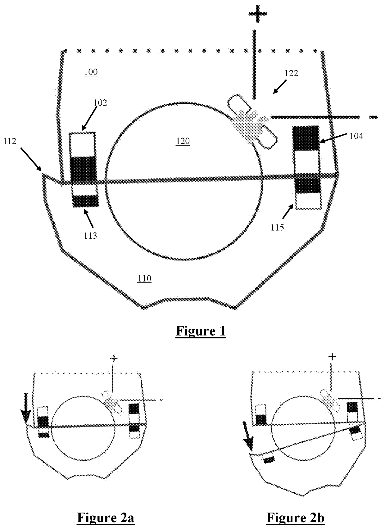
[0077]FIG. 1 is a cross sectional view of a battery cover 110 and battery compartment 100 in accordance with a first embodiment of the present invention. The described embodiments provide a magnetic replaceable battery compartment for a hearing aid. More specifically, a modular battery case to store and facilitate connection between the hearing aid and a replaceable battery is presented. The compartment 100 and cover 110 are held together by magnets 102, 104, 113, 115. Throughout the drawings, for illustrative purposes, permanent magnets are depicted using black fill for the magnetic north end of the magnet and white fill for the magnetic south end of the magnet. Alternative embodiments may equivalently or similarly reverse the polarity of all or some of the magnets shown, and / or may replace a suitable subset of the described permanent magnets with any suitable magnetic restraint element such as a steel plate.

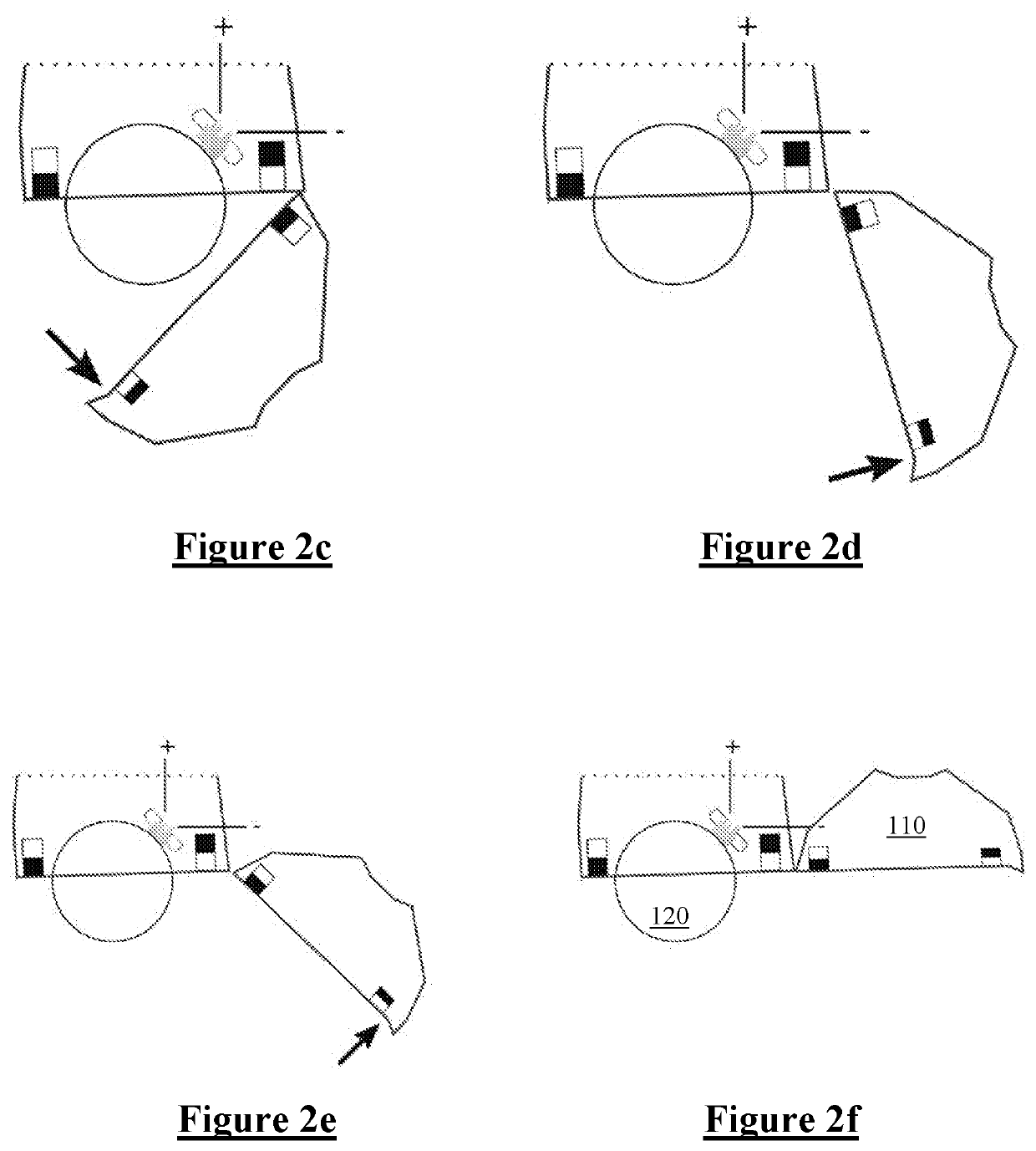
[0078]The compartment 100 and cover 110 together define a circular battery...


PUM


Abstract

A hearing device comprises a device body carrying a hearing device processor for processing microphone signals to produce an output acoustic signal for delivery to a respective ear of a user. A battery compartment is provided for containing a battery to power the processor, the battery compartment bearing at least two magnets, or magnetic restraint elements. A battery cover bearing at least two magnets respectively configured to magnetically cooperate with the at least two battery compartment magnets in order to magnetically hold the battery cover against the battery compartment so as to define a battery cavity between the battery cover and the battery compartment. The magnets are positioned about the battery cavity so as to magnetically urge the battery cover to a preferred position relative to the battery compartment.

Description

CROSS-REFERENCE TO RELATED APPLICATIONS[0001]This application claims the benefit of Australian Provisional Patent Application No. 2017900266 filed 31 Jan. 2017, which is incorporated herein by reference.TECHNICAL FIELD[0002]The present invention relates to a method and device for incorporating a replaceable battery in a hearing device. In particular the present invention provides a battery compartment using magnets to ease the task of removing and replacing the replaceable battery.BACKGROUND OF THE INVENTION[0003]Hearing devices such as hearing aids and assistive listening devices (ALDs) are typically designed with a device lifetime of about 5 years. With device miniaturisation very limited space is available for a battery to power the device. Rechargeable batteries which are small enough for use in hearing devices only have sufficient power for about one or two days of device operation, and typically can only be recharged about 500 times. Accordingly, a single rechargeable battery ...

Claims


Application Information

Patent Timeline
Patent Type & Authority Applications(United States)
IPC IPC(8): H04R25/00B33Y80/00
CPCB33Y80/00B33Y50/00H04R25/602H04R2225/31H04R25/609H04R2225/77H04R25/55H04R2225/61H04R25/603
Inventor KAUFMAN, YANIV ELIEZER
Owner SONOVA AG
Why Eureka
Try Eureka