Air exhausting mechanism for mobile illuminating lighthouse

a technology of air exhausting mechanism and lighthouse, which is applied in the direction of electric generators, electric lighting with built-in generators, lighting and heating apparatus, etc., to avoid the safety impact of direct air exhausting on the operator and reduce nois

Inactive Publication Date: 2020-01-02
ATLAS COPCO WUXI COMPRESSOR
View PDF5 Cites 0 Cited by
  • Summary
  • Abstract
  • Description
  • Claims
  • Application Information

AI Technical Summary

Benefits of technology

This patent application describes an air exhausting mechanism for a mobile illumination light tower that helps to safely release hot air in the vehicle and ensures the operator's safety. The mechanism changes the air exhausting direction to downward air exhausting via the hood, which reduces the risk of injury from direct air exhausting. It also discharges the hot air outside the vehicle after it has cooled, and a silencing layer is provided to reduce the noise to make the mobile illuminating light tower more environmentally friendly. Overall, the air exhausting mechanism makes the mobile illuminating light tower safer and environmentally friendly.

Problems solved by technology

Since the hot air is directly discharged and the safety of the operator will also be affected, it is necessary to avoid the air exhausting area as much as possible during use.

Method used


Image

  • Air exhausting mechanism for mobile illuminating lighthouse
  • Air exhausting mechanism for mobile illuminating lighthouse

Examples


Embodiment Construction

[0017]Specific embodiments of the present invention will be described in detail below with reference to the accompanying drawings.

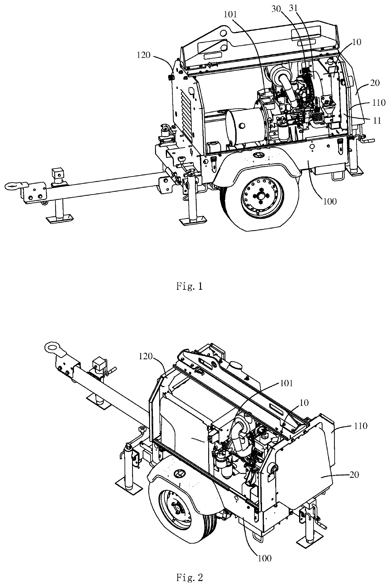
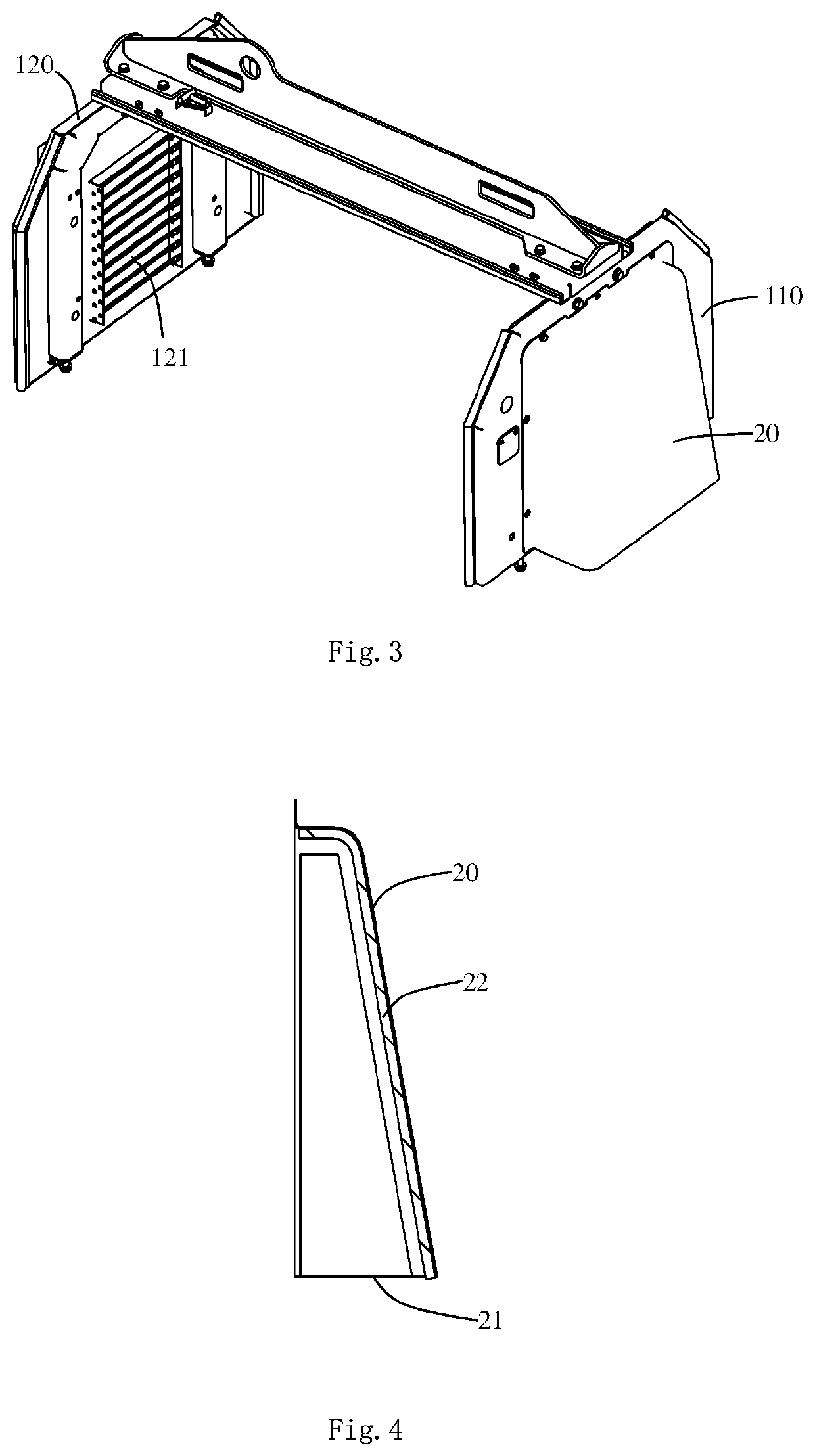
[0018]As shown in FIG. 1 to FIG. 4, an air exhausting mechanism for a mobile illuminating light tower of the present patent application comprises a cooler 10, an air discharge hood 20, and a fan 30. The cooler 10 and the air discharge hood 20 are respectively disposed on two sides of a rear canopy panel 110 of the mobile illuminating light tower. The cooler 10 is mounted on a bottom plate 100 of the mobile illuminating light tower and located on an inner side of the rear canopy panel 110. The air discharge hood 20 is fixedly mounted on an outer side of the rear canopy panel 110. The cooler 10 is preferably fixed to the bottom plate 100 by a mounting bracket 11. The mounting bracket 11 and the rear canopy panel 100 may be fixed together, or the mounting bracket 11 and the rear canopy panel 100 may be respectively fixed on the bottom plate 100.

[0019]The coo...


PUM


Abstract

An air exhausting mechanism for a mobile illuminating light tower includes a cooler, an air discharge hood, and a fan. The cooler and the air discharge hood are respectively disposed on two sides of a rear canopy panel. The cooler is mounted on a bottom plate, and is located on the inner side of the rear canopy panel. The air discharge hood is fixedly mounted on the outer side of the rear canopy panel. The cooler is provided with an air inlet and an air outlet. An air exhausting groove is formed in the rear canopy panel. The fan is disposed at the air inlet of the cooler. The air exhausting groove is opposite to the air outlet. The air discharge hood covers the air exhausting groove, and the bottom of the air discharge hood is open. The mobile illuminating light tower is safe and environmentally friendly.

Description

TECHNICAL FIELD[0001]The present patent application relates to a mobile illuminating light tower, and more particularly, to an air exhausting mechanism for a mobile illuminating light tower.BACKGROUND[0002]A mobile illuminating light tower is used for road illuminating, industrial-place illuminating, flood illuminating of building exteriors and for commercial illuminating and industrial illuminating outdoors.[0003]The generator set of the mobile illuminating light tower is installed in the vehicle body. Heat will be generated when the generator set works, and the heat in the vehicle body needs to be discharged. At present, the method to provide an air exhausting groove on the canopy panel of the vehicle body to facilitate the ventilation of the interior of the vehicle body so as to discharge the heat is usually adopted. Several air exhausting grooves are usually respectively provided on the front canopy panel and the rear canopy panel for heat dissipation in order to enhance air flo...

Claims


Application Information

Patent Timeline
Patent Type & Authority Applications(United States)
IPC IPC(8): F21V29/67F21L13/00F21V29/502
CPCF21W2131/10F21L13/00F21V29/677F21V29/502F21V29/508F21V29/67F21L14/04
Inventor LI, QIANGYU, XIALU, DEZHONGCONG, HAIYING
Owner ATLAS COPCO WUXI COMPRESSOR
Why Eureka
Try Eureka