Lighting concept for a charging park

a charging park and concept technology, applied in charging stations, electric vehicle charging technology, transportation and packaging, etc., can solve the problems of limited evaluation of received signals of light sensors, and achieve the effect of increasing the cooling capacity of the charging column in question, reducing the risk of failure, and increasing the degree of failsafety

Active Publication Date: 2020-01-02
DR ING H C F PORSCHE AG
View PDF0 Cites 2 Cited by
  • Summary
  • Abstract
  • Description
  • Claims
  • Application Information

AI Technical Summary

Benefits of technology

[0019]According to further exemplary embodiments, the method can further comprise controlling a cooling circuit of the charging station depending on the result of the comparison of the ascertained temperatures of the charging columns with the ascertained brightness values of the charging columns. In other words, on the basis of solar irradiation of a charging column, in particular of the charging cable of the charging column, which solar radiation is ascertained by brightness and preferably verified by temperature measurement, a cooling circuit can be actuated in such a way that the cooling capacity at the charging column in question is increased. Excessive heating of the charging column, which can cause a malfunction, can thereby be avoided.
[0020]Overall, efficient fault identification can take place by comparing the signals or data of a light sensor with the results which are obtained from collectively evaluating the signals or data of all or at least a group of the majority of light sensors (with or without the inclusion of the light sensor under consideration, of which the signals or data are / is compared) and a higher degree of fail-safety can be achieved by compensating for the missing / incorrect signals or data at the same time. In general, non-optimum or even faulty actuation of a display and / or of a lighting means on the basis of false brightness information of a defective light sensor can be avoided by comparing the measurement values of the light sensors with results of collectively evaluating the measurement values of the other light sensors (for example a mean value).

Problems solved by technology

Evaluating the received signals of the light sensors can be limited to any desired subgroup of light sensors and therefore any desired subgroup of charging columns of the charging park.
In particular, disadvantages due to location of individual charging columns within the charging column ensemble can be identified and taken into account when actuating the displays and / or lighting means.

Method used


Image

  • Lighting concept for a charging park

Examples


Embodiment Construction

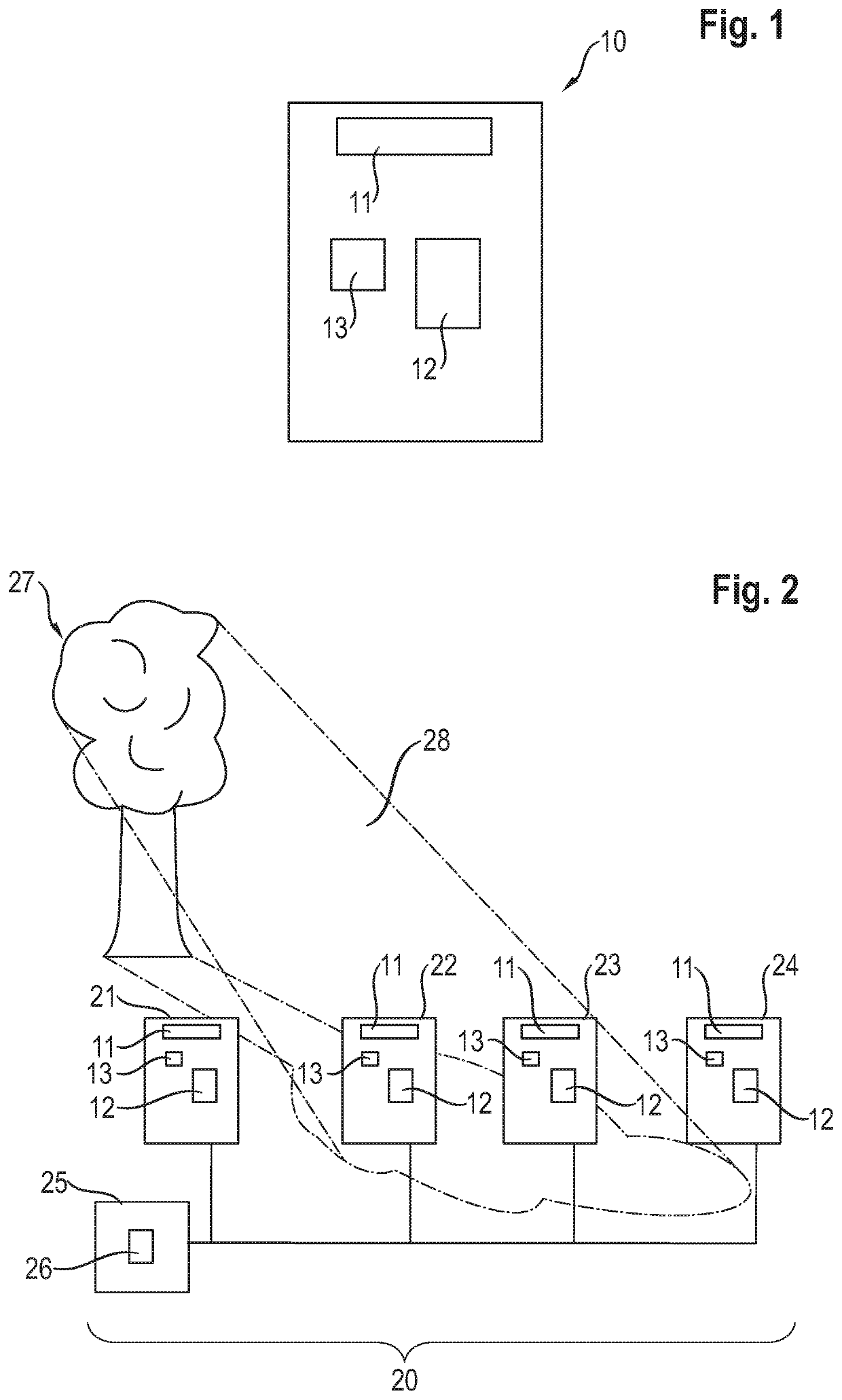
[0027]FIG. 1 shows a schematic view of a charging column 10 which can be used within the scope of the method according to aspects of the invention. The charging column 10 has a lighting means 11 which is provided for illuminating the region around the charging column 10. Furthermore, the charging column 10 has a user interface 12 by means of which a user can carry out a charging process on the charging column 10. The user interface 12 may be a display means, for example a touch-sensitive screen. The charging column 10 further has a light sensor 13 for detecting the brightness level prevailing on the charging column 10. The charging column 10 additionally has a charging cable which, however, is not explicitly illustrated in FIG. 1.

[0028]FIG. 2 shows an exemplary charging park 20 which comprises four charging columns 21-24, wherein each of the charging columns 21-24 can correspond to the charging column shown in FIG. 1. The charging columns 21-24 constitute structurally and physically...


PUM


Abstract

A method for operating a charging system for charging electric vehicles, wherein the charging system has a charging station and at least two charging columns which are physically separate from one another and each have at least one charging connection. Each charging column has a light sensor and also a light and/or a display. The method includes receiving signals of the individual light sensors and also collectively evaluating the signals and adjusting the brightness of the light and/or the display of at least one of the charging columns depending on a result of collectively evaluating the received signals. Also described herein is a corresponding charging system.

Description

CROSS-REFERENCE TO RELATED APPLICATION[0001]This application claims priority to German Patent Application No. DE 10 2018 115 797.5, filed Jun. 29, 2018, which is incorporated by reference herein in its entirety.FIELD OF THE INVENTION[0002]The present invention relates, in general, to a lighting concept for a charging park, in particular to a method for controlling lighting and / or display means on charging columns of the charging park, which method depends on the ambient brightness.BACKGROUND OF THE INVENTION[0003]Nowadays, charging columns for charging electric vehicles are often installed sporadically, especially since there is usually no power grid connection which allows a plurality of charging columns to be installed in one place. These sporadically installed charging columns are individually operated and are not understood to be a charging park. However, as the number of electric vehicles increases, the demands made on the charging infrastructure also increase. In the manner of...

Claims


Application Information

Patent Timeline
Patent Type & Authority Applications(United States)
IPC IPC(8): B60L53/68B60L53/30B60L53/302B60L53/67H05B37/02
CPCB60Y2200/91B60L53/67B60L53/68B60L53/302B60L53/14B60Y2300/91H05B37/0218B60L53/305B60L53/30B60L2250/16Y02B20/40Y02T90/16Y02T10/70Y02T10/7072Y02T90/12Y02T90/14H05B47/11
Inventor ZANDER, STEVEKAUL, TIMOHEYNE, RAOUL
Owner DR ING H C F PORSCHE AG
Why Eureka
Try Eureka