
Method for inspecting separation membrane module and method for manufacturing separation membrane module

a technology of separation membrane and inspection method, which is applied in the direction of separation process, dispersed particle separation, chemistry apparatus and processes, etc., can solve the problems of adverse effect on the permeation characteristics of the separation membrane after, and inability to accurately inspect gas leakage, etc., to suppress the reduction in the permeation characteristics of the separation membrane, the effect of accurate inspection of gas leakag

Pending Publication Date: 2020-01-02
NGK INSULATORS LTD
View PDF0 Cites 2 Cited by
  • Summary
  • Abstract
  • Description
  • Claims
  • Application Information

AI Technical Summary

Benefits of technology

This patent describes methods for making and testing separation membrane modules that can accurately detect gas leaks while maintaining the membrane's ability to pass gas.

Problems solved by technology

However the method disclosed in Japanese Patent Application Laid-Open No. 2004-216284 does not consider the relationship between the pore diameter of the separation membrane and the molecular diameter of the gas for inspection.
Therefore, it may be the case that the gas for inspection passes through the pores of the separation membrane and an accurate inspection of gas leak is not possible.
Furthermore, the method disclosed in Japanese Patent Application Laid-Open No. 2004-216284 does not consider the adsorption or condensation properties of the gas for inspection relative to the separation membrane.
It may be the case that pores will become blocked by adsorption or condensation of the gas for inspection onto the separation membrane and therefore there will be an adverse effect on the permeation characteristics of the separation membrane after the inspection.

Method used


Image

  • Method for inspecting separation membrane module and method for manufacturing separation membrane module
  • Method for inspecting separation membrane module and method for manufacturing separation membrane module
  • Method for inspecting separation membrane module and method for manufacturing separation membrane module

Examples


examples

[0080]Sample No. 1

[0081]1. Preparation of Separation Membrane Structure

[0082]Firstly, 30 vol % of an inorganic binding material was added to 70 vol % of alumina particles (aggregate) having an average particle diameter of 12 μm. Then, a molding auxiliary agent such as an organic binder or the like and a pore forming agent were added and dry mixed. Water and a surface active agent were added, and the mixture was mixed and kneaded to prepare a clay. The inorganic binding material includes use of talc, kaolin, feldspar, clay or the like having an average particle diameter of 1 to 5 μm to form a mixture of SiO2 (70 mass %), Al2O3 (16 mass %), alkali earth metals and alkali metals (11 mass %).

[0083]Next, the clay was extrusion molded to thereby prepare a green body for a monolithic porous body. Then, the green body for the porous body was fired (1250 degrees C., one hour) to thereby obtain an alumina substrate having a large number of cells.

[0084]Next, PVA (organic binder) was added to t...


PUM


Abstract

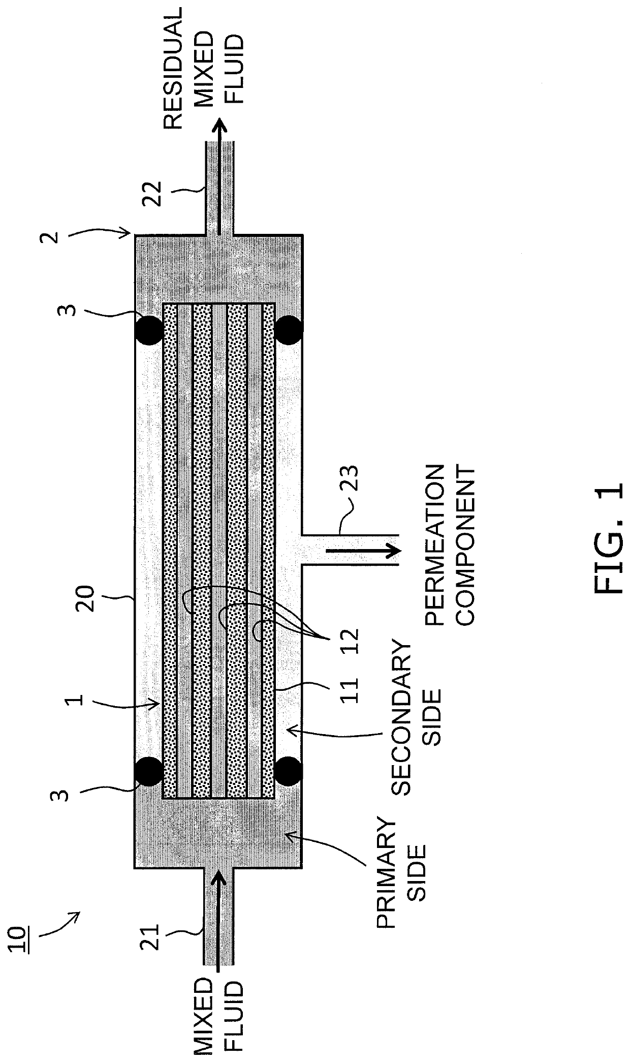
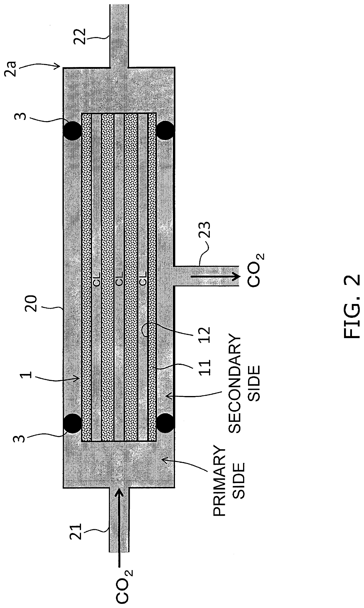
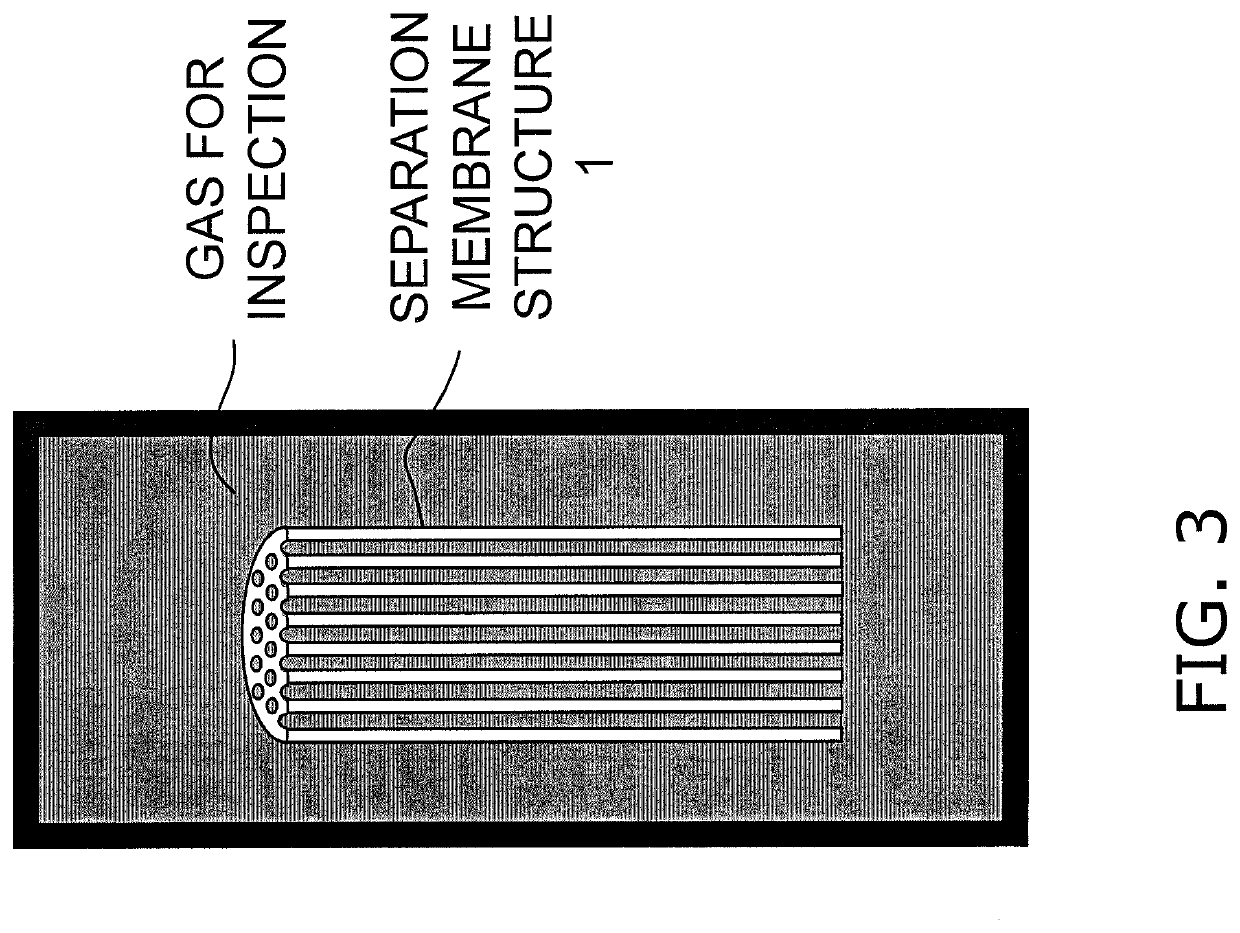
A method for inspecting a separation membrane module has a sealing step for sealing a gas for inspection on a primary side of zeolite membrane. The dynamic molecular diameter for the gas for inspection is greater than 1.07 times the pore diameter in the zeolite membrane. The gas for inspection has the characteristic of having a rate of reduction for a CO2 gas permeation rate in the zeolite membrane of less than 10% when a separation membrane structure is allowed to stand for 60 minutes in the gas for inspection at 25 degrees C. and 0.1 MPaG.

Description

TECHNICAL FIELD[0001]The present invention relates to a method for inspecting a separation membrane module and to a method for manufacturing a separation membrane module.BACKGROUND ART[0002]Japanese Patent Application Laid-Open No. 2004-216284 discloses a method of inspecting a gas leak in a separation membrane module based on a pressure change in a gas for inspection that is sealed in a primary side of a separation membrane in a separation membrane module in which a separation membrane configured as a hollow fiber membrane is assembled into a casing.SUMMARY[0003]However the method disclosed in Japanese Patent Application Laid-Open No. 2004-216284 does not consider the relationship between the pore diameter of the separation membrane and the molecular diameter of the gas for inspection.[0004]Therefore, it may be the case that the gas for inspection passes through the pores of the separation membrane and an accurate inspection of gas leak is not possible.[0005]Furthermore, the method...

Claims


Application Information

Patent Timeline
IPC IPC(8): B01D53/22B01D63/06B01D65/10
CPCB01D65/102B01D53/228B01D69/10B01D63/06B01D2256/245B01D2257/504B01D65/104B01D63/066Y02C20/40B01D71/0281
Inventor SHIMIZU, KATSUYAICHIKAWA, MAKIKOYAJIMA, KENJIHAGIO, TAKESHI
Owner NGK INSULATORS LTD
Learn More