
Modular three-dimensional optical sensing system

a three-dimensional optical sensing and module technology, applied in the field of photonic integrated circuits, can solve the problems of high manufacturing cost, high cost and difficulty in manufacturing specialized ingaas high speed, mirror based approaches typically suffer speed and reliability problems, etc., and achieve the effect of less challenging implementation and ease of system integration

Active Publication Date: 2019-12-26
POINTCLOUD INC
View PDF36 Cites 50 Cited by
  • Summary
  • Abstract
  • Description
  • Claims
  • Application Information

AI Technical Summary

Benefits of technology

The patent describes a new system that solves problems with traditional LIDAR architectures by using on-chip integration and addressing scalability and practical integration issues. The system also proposes a novel all solid state beam steering approach that has the speed and reliability advantages of Optical Phased Arrays, but is significantly less challenging to implement in an integrated platform. A modular architecture is also proposed for the system with modules connected through a fiber optic network, which eases integration of the system within an automotive platform and removes design constraints. The patent also describes a method for providing a frequency chirped light beam by using a continuous wave light source and dividing the light beam into two parts, modulating each in-phase and in-quadrature, and combining them to form a frequency chirped light beam with a phase shift and reduced relative phase offset. The patent also describes generating multiple frequency chirps simultaneously or sequentially.

Problems solved by technology

The disadvantage of the above approaches is the large number of discrete parts leading to high cost of manufacturing.
The main disadvantage of such a system is the high cost and difficult manufacturing of the specialized InGaAs high speed, high sensitivity detector arrays.
Mirror based approaches typically suffer from speed and reliability problems while Optical Phased Arrays have proven technologically very difficult to implement for optical domain electromagnetic waves.

Method used


Image

  • Modular three-dimensional optical sensing system
  • Modular three-dimensional optical sensing system
  • Modular three-dimensional optical sensing system

Examples


Embodiment Construction

[0095]System Block Diagram

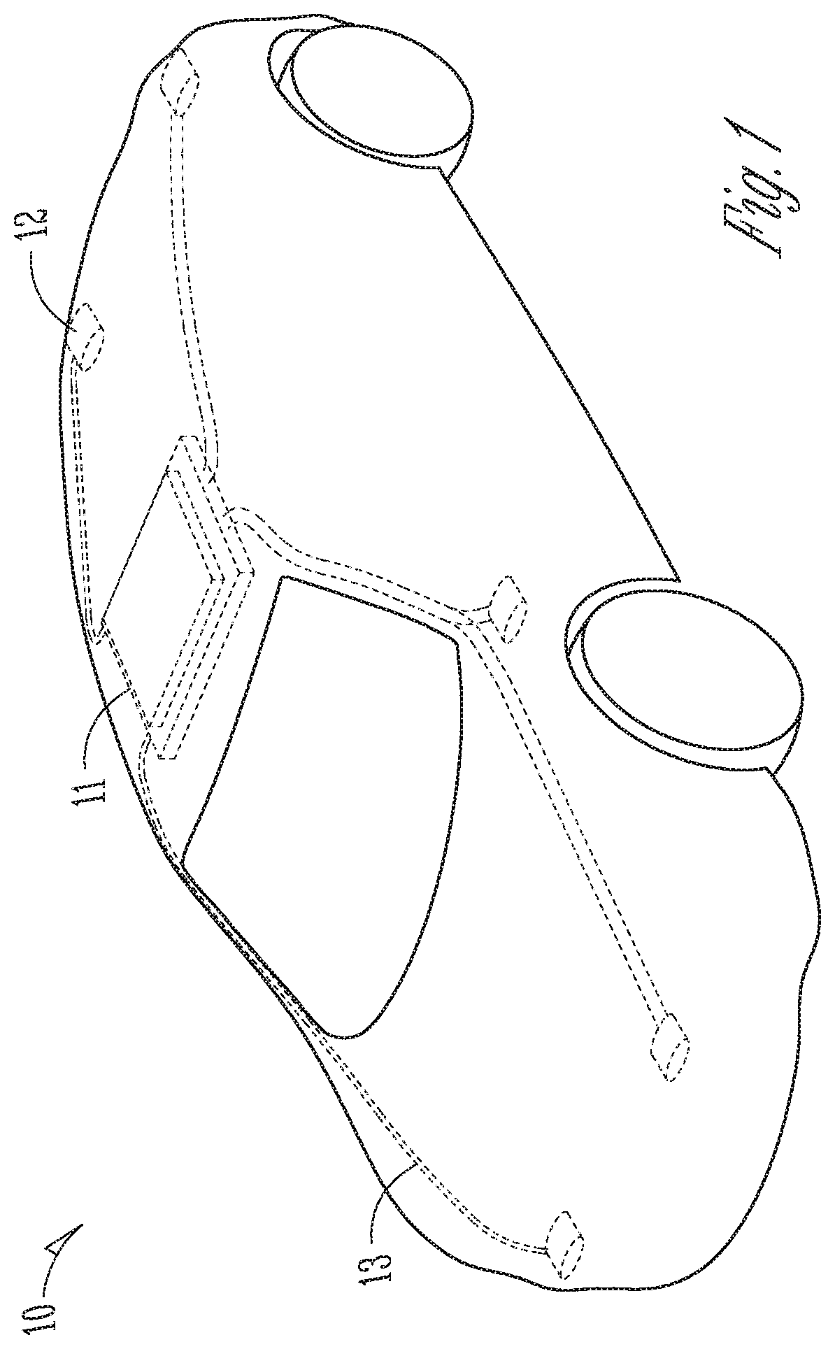
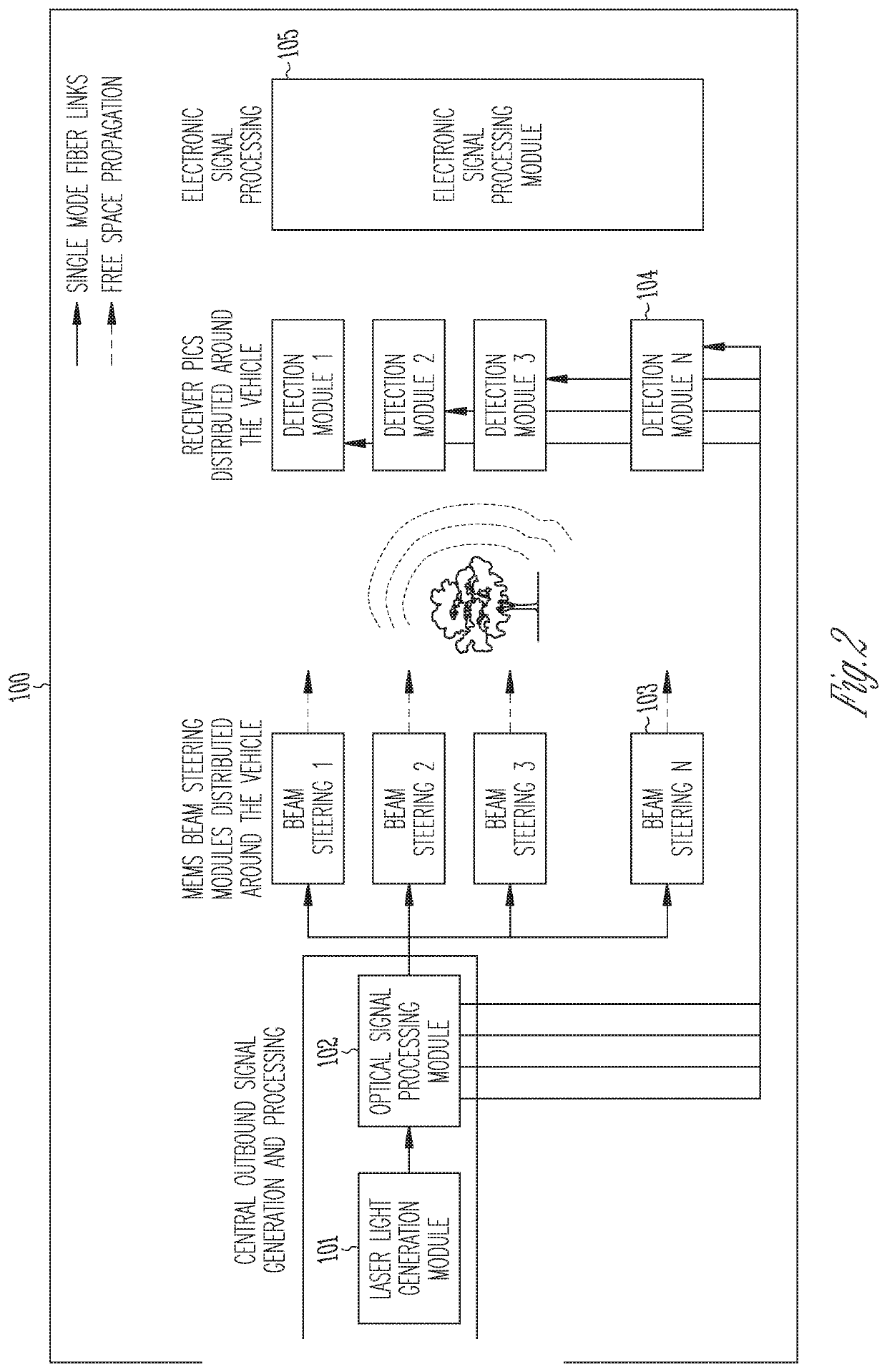
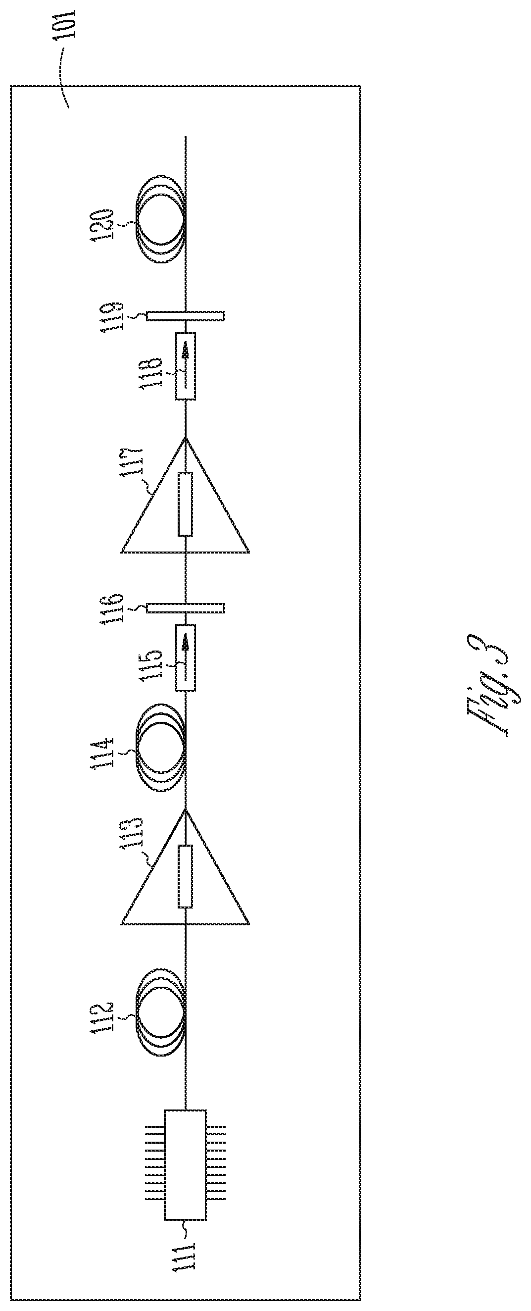
[0096]FIG. 2 is a block diagram that illustrates a LIDAR system 100, according to an example. The LIDAR system 100 includes the following: a laser light generation module 101, an optical signal processing module 102, a plurality of beam steering modules 103, a plurality of detection modules 104, and an electronic signal processing module 105. The laser light generation module 101 produces laser light with defined spectral and power characteristics. The light can be transmitted via optical fiber to an optical signal processing module 102, which in an example includes a photonic integrated circuit (PIC), which performs a plurality of passive and active optical functions to create one or multiple optical signals with tailored amplitude, phase and spectral characteristics. Advantages of using a transmitter PIC include the ability to have complex processing of the optical signal and increasingly complex functionality for lower cost and higher performance compare...


PUM

PropertyMeasurementUnit
wavelengthaaaaaaaaaa
poweraaaaaaaaaa
wavelengthaaaaaaaaaa

Abstract

Examples of a three-dimensional (3D) optical sensing system for a vehicle include a modular architecture. Light can be transmitted to an optical signal processing module, which can include a photonic integrated circuit (PIC) that can create one or more signals with tailored amplitude, phase, and spectral characteristics. The plurality of optical signals processed by the optical signal processing module can be sent to beam steering units distributed around the vehicle. The steering units can direct a plurality of optical beams towards targets. The return optical signal can be detected by a receiver PIC including an array of sensors and using a direct intensity detection technique or a coherent detection technique. The return optical signal can be converted into an electrical signal by the array of sensors, which can then be processed by the electronic signal processing unit, and information about the location and speed of the targets can be quantified.

Description

CLAIM OF PRIORITY[0001]This application claims the benefit of priority of U.S. Provisional Patent Application Ser. No. 62 / 465,197, filed Mar. 1, 2017, U.S. Provisional Patent Application Ser. No. 62 / 491,443, filed Apr. 28, 2017, U.S. Provisional Patent Application Ser. No. 62 / 573,360, filed Oct. 17, 2017, and U.S. Provisional Patent Application Ser. No. 62 / 608,183, filed Dec. 20, 2017, which are hereby incorporated by reference herein in their entirety.FIELD OF THE DISCLOSURE[0002]The disclosure generally relates to photonic integrated circuits, such as for automotive lidar.BACKGROUND[0003]Examples relate to the general field of light detection and ranging (LIDAR) 3D imaging and more specifically to detailed 3D mapping of the environment for autonomous vehicles.[0004]Two alternative approaches are typically used to measure the coordinates of a remote target and create a 3D image of an object or environment: one based on time of flight measurements of a short pulse or pulse successio...

Claims


Application Information

Patent Timeline
Patent Type & Authority Applications(United States)
IPC IPC(8): G01S7/481G01S17/32G02F1/29G01S17/89G01S7/491G01S7/4863G01S7/4911G01S7/4914G01S17/18G01S17/34G01S17/931
CPCG02F2203/50G02F1/292G01S7/4817G01S7/4911G01S17/32G01S17/89G02F2203/24G01S17/42G01S7/4808G01S7/484G01S7/4863G01S7/4914G01S17/18G01S17/34G01S17/931
Inventor NICOLAESCU, REMUS
Owner POINTCLOUD INC
Learn More