
Sound-absorbing device

a technology of sound absorption device and sound absorption chamber, which is applied in the direction of sound absorption, lighting and heating apparatus, building components, etc., can solve the problems of affecting conversation and therefore attenuation, insufficient lighting, and inability to absorb sound in free spaces created in this way, so as to achieve the effect of attenuating the noise level of disturban

Inactive Publication Date: 2019-12-26
LTS LICHT & LEUCHTEN
View PDF0 Cites 0 Cited by
  • Summary
  • Abstract
  • Description
  • Claims
  • Application Information

AI Technical Summary

Benefits of technology

The present invention aims to develop a sound-absorbing device that can effectively absorb sound waves while providing sufficient lighting for the interior of a room. The device has a cover plate that serves as a support against gravity, allowing for easy assembly without additional fastening elements. The flat structures embedded within the frame prevent the reflection of sound waves and the disturbing noise levels that may occur. The arrangement of lighting means in two parallel rows requires minimal space and allows for better sound-absorbing properties. These technical effects make the device ideal for reducing noise in buildings and providing improved acoustic quality.

Problems solved by technology

In conference rooms in particular, it has been found that the background noise caused by sound waves can disrupt the conversation and must therefore be attenuated.
The flat structures equipped with sound-absorbing properties have proved their worth in practice for absorbing sound waves, but such rooms often require sufficient lighting, as documents must be viewed inside them.
However, these free spaces created in this way do not have any sound-absorbing properties; rather, the sound waves reach the ceiling unhindered and are reflected back into the interior of the room by it.
The more free spaces are needed to create the necessary lighting, the more disturbing are the ambient noises caused by the sound, since the sound waves enter the interior of the room in a correspondingly large number.

Method used


Image

  • Sound-absorbing device
  • Sound-absorbing device
  • Sound-absorbing device

Examples


Embodiment Construction

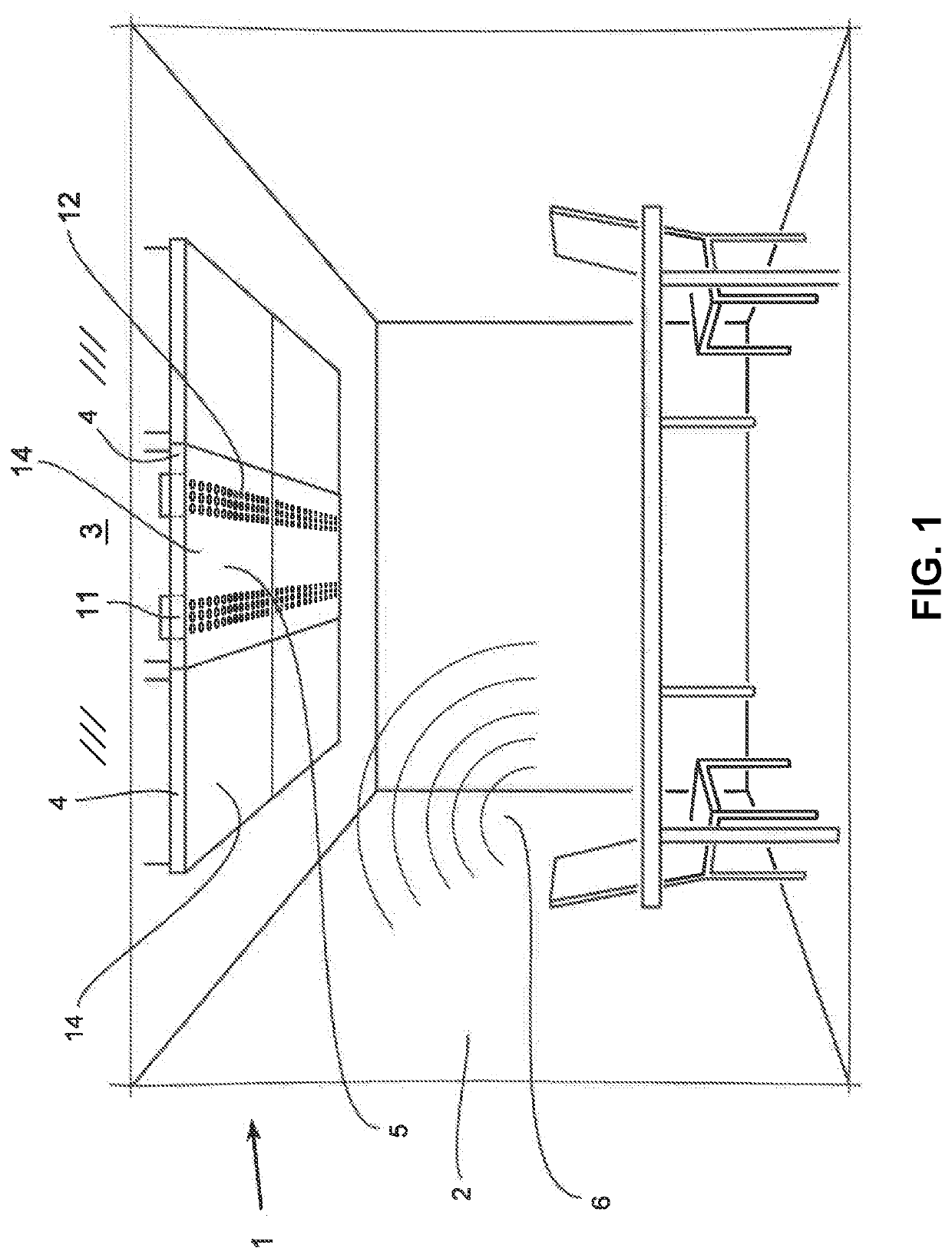
[0017]FIG. 1 shows a schematic view of a usual meeting situation in a room 2, in which two devices 1 in accordance with the present invention are suspended from the ceiling 3 of the room 2 by means of which, for example, sound waves 6 generated by conversations are absorbed, so that they are not reflected back into the interior of the room by the ceiling 3 and, at the same time, sufficient illumination of the room 2 should be set.

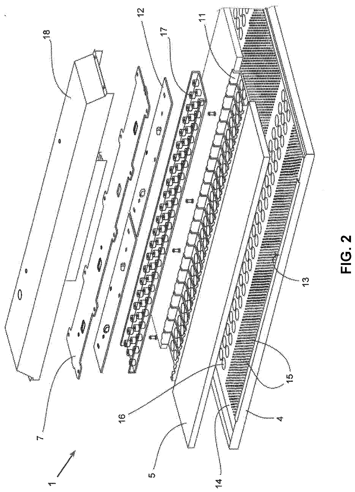
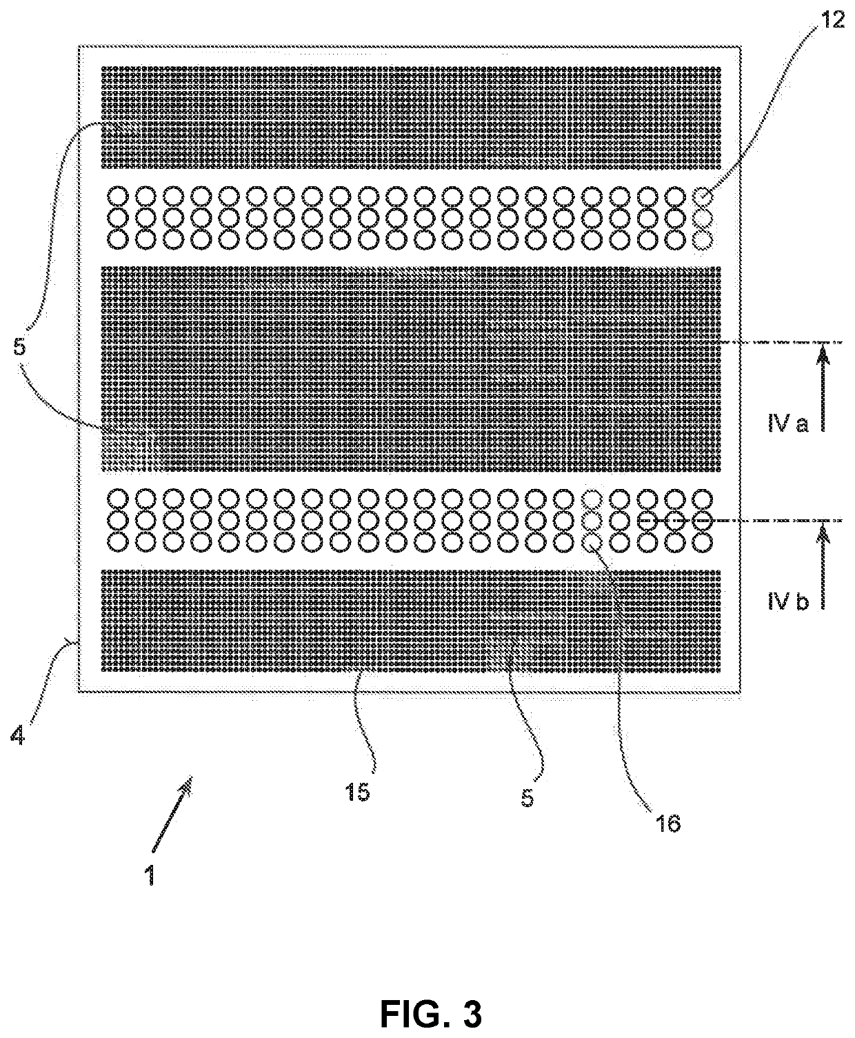
[0018]The device 1 consists of three flat structures 5 which are inserted into a frame 4 which is placed at a distance from the ceiling 3 and parallel to it. The frame 4 can have an L-shaped cross-sectional structure, so that the respective flat structures 5 are supported by the surrounding frame 4. The frames 4 suspended from the ceiling 3 adjacent to the device 1 in the invention have the same outer dimensions, but consist exclusively of a relevant flat structure 5, so that they are used exclusively for sound absorption.

[0019]The device 1 in accordance wi...


PUM


Abstract

In a sound-absorbing device (1) which is suspended from ceilings (3) in rooms (2), comprisinga frame (4) which is fastened at a distance from the ceiling (3) and parallel thereto, andat least one flat structure with sound-absorbing properties which is inlaid or inserted into the frame (4),on the one hand a sound-absorbing property should be present as far as possible over the entire surface of the ceiling (3) and on the other hand sufficient illumination should be possible for the interior of the room. This is solved in accordance with the present invention by at least one intermediate space (11) being provided in the flat structure (5), by one or more lighting means (12) being arranged in the respective intermediate space (11), and by each of the lighting means (12) being locked to the frame (4) directly or by means of support elements (13).

Description

REFERENCE TO PENDING PRIOR PATENT APPLICATION[0001]This patent application claims benefit of European Patent Application No. 18 179 469.4, filed Jun. 25, 2018, which patent application is hereby incorporated herein by reference.FIELD OF THE INVENTION[0002]The present invention refers to a sound-absorbing device which is mounted at a distance from ceilings of rooms and parallel to them.BACKGROUND OF THE INVENTION[0003]In conference rooms in particular, it has been found that the background noise caused by sound waves can disrupt the conversation and must therefore be attenuated. For this reason, rooms with correspondingly large dimensions are often clad with flat structures that have a sound-absorbing property in order to attenuate or absorb the sound waves generated during conversations. These flat structures are inlaid or inserted into a frame and the frame is attached to the ceiling by means of wires or pipe sections, for example.[0004]The flat structures equipped with sound-absor...

Claims


Application Information

Patent Timeline
IPC IPC(8): E04B1/84F21V33/00
CPCE04B2001/8433F21V33/0056E04B1/84E04B2001/8263E04B2001/8452E04B1/86E04B9/001E04B9/006E04B9/0428E04B9/0457E04B9/0464E04B9/0485F21V33/006E04B1/8209F21Y2115/10F21Y2105/16
Inventor STEINEL, EWALD
Owner LTS LICHT & LEUCHTEN
Learn More