
Dental implant positioning and guiding assembly

a technology for positioning and guiding parts, which is applied in dentistry, dental surgery, medical science, etc., can solve the problems of high cost, inability to use a common dimension for mass production, and inability to quickly complete dental implant surgery, so as to reduce the possibility of future dental implant complications, improve clinical operation flexibility, and cost

Inactive Publication Date: 2019-12-12
SICHUAN HONGZHENGBOEN DENTAL TECH CO LTD
View PDF3 Cites 1 Cited by
  • Summary
  • Abstract
  • Description
  • Claims
  • Application Information

AI Technical Summary

Benefits of technology

The present invention provides a dental implant positioning and guiding assembly that can provide complete pre-surgical information, including buccal-lingual position, mesial-distal position, direction, and angle. This helps the dentist access the best position of the implant hole, reducing the possibility of future dental implant complications and improving flexacity and cost-effectiveness. The assembly includes a guiding element that can be adjusted to various positions and angles, making the implant procedure safer, efficient, and comfortable for the patient. The guiding element simplifies the complicated manufacturing process of implant guide and enhances the success rate of the dental implant surgery. The concave element and the positioning rod can be easily positionally assembled and disassembled without the need to repeatedly take off the implant guide. This saves surgical time and makes the operation more convenient.

Problems solved by technology

In view of the aforementioned problems of the conventional art that the implant precision for the dental implant surgery is low, the dental implant surgery cannot be completed rapidly and thoroughly right beside the dental chair, and the technology of full mouth digitized 3D printed guide needs a whole set of full mouse scan guide to be printed for both single missing tooth and multiple missing teeth, is unable to use a common dimension for mass production, has a high cost and a long waiting time is long.

Method used


Image

  • Dental implant positioning and guiding assembly
  • Dental implant positioning and guiding assembly
  • Dental implant positioning and guiding assembly

Examples


Embodiment Construction

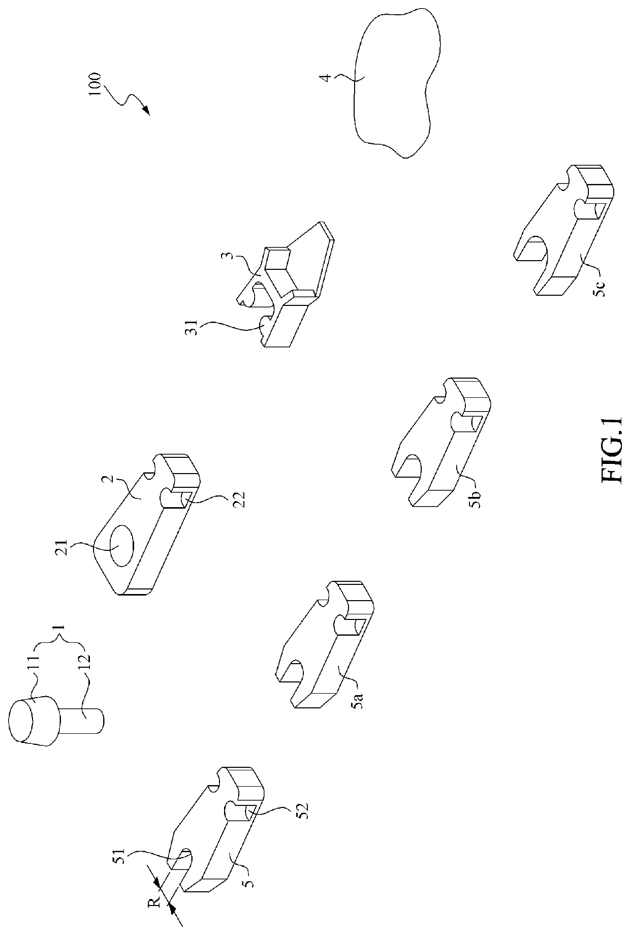
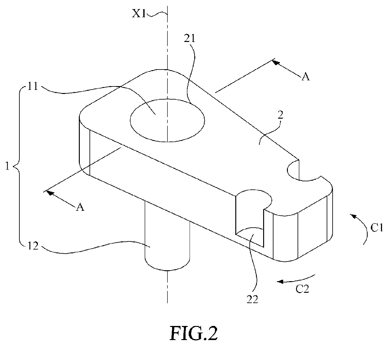
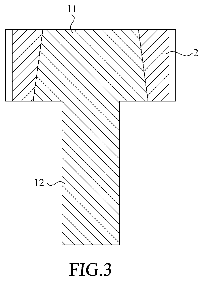
[0032]Please refer to FIG. 1 to FIG. 3, wherein FIG. 1 is a perspective schematic view of a dental implant positioning and guiding assembly in accordance with a preferred embodiment of the present invention; FIG. 2 is a schematic view showing the assembly of the positioning rod and the convex element of the dental implant positioning and guiding assembly in accordance with a preferred embodiment of the present invention; and FIG. 3 is a schematic view showing the cross section A-A in FIG. 2. As shown, the dental implant positioning and guiding assembly 100 comprises a positioning rod 1, a convex element 2, a concave element 3, a connector 4, and four guiding elements 5, 5a, 5b, and 5c. In the present embodiment, the positioning rod 1, the convex element 2, the concave element 3, and the guiding elements 5, 5a, 5b and 5c are manufactured by using 3D printing technology, however, the present invention is not limited thereto. For example, these elements can be manufactured by using cer...


PUM


Abstract

A dental implant positioning and guiding assembly is disclosed in the present invention. The dental implant positioning and guiding assembly includes a positioning rod, a convex element, a concave element, a connector and a plurality of guiding elements. The positioning rod is utilized to be inserted into a drilled hole in a patient's oral model. The convex element has a through hole for holding the positioning rod. The concave element is positionally assemble with the convex element. The connector is fixed to one side of the concave element and has a contact surface with a surface contour matching an oral contour of the patient for engaging with the oral contour. Each of the guiding elements is positionally assembled with the concave element and has an open with a curve guiding surface for guiding the surgery operator to drill the at least one implant hole.

Description

[0001]This application claims the benefit of Taiwan Patent Application Serial No. 107119880, filed Jun. 8, 2018, the subject matter of which is incorporated herein by reference.BACKGROUND OF INVENTION1. Field of the Invention[0002]The present invention is related to a positioning and guiding assembly, and more particularly is related to a dental implant positioning and guiding assembly.2. Description of the Prior Art[0003]Dental implant surgery is a procedure using an implant with a lower portion thereof interfaces with the bone as a basis to support and position a dental prosthesis on the upper portion of the implant. Because of the function, structure, and cosmesis of the implant is quite similar to the natural teeth, dental implant surgery has become the first recovery choice for the patient with missing teeth. Before the placing the implant, the dentist needs to drill an implant hole in the alveolar bone for placing the implant through the dental implant surgery. The dentist nee...

Claims


Application Information

Patent Timeline
Patent Type & Authority Applications(United States)
IPC IPC(8): A61C1/08
CPCA61C1/084
Inventor WANG, HOM-LAYDAI, DEBBY
Owner SICHUAN HONGZHENGBOEN DENTAL TECH CO LTD
Learn More