
Light emitting diode chip having distributed bragg reflector

Active Publication Date: 2019-12-05
SEOUL VIOSYS CO LTD
View PDF2 Cites 0 Cited by
  • Summary
  • Abstract
  • Description
  • Claims
  • Application Information

AI Technical Summary

Benefits of technology

This patent discusses how devices made using certain techniques can improve the efficiency of light emitting diodes. These devices have a special structure called a DBR that helps to reduce the loss of light from absorption. The result is that the devices can produce light that is brighter and more effective.

Problems solved by technology

A metal reflector, such as Al, provides an even reflectance for incident light of various wavelengths, but the reflectance of the metal reflector may be deteriorated from oxidation or the like, and may have relatively low reflectance with the passage of time.
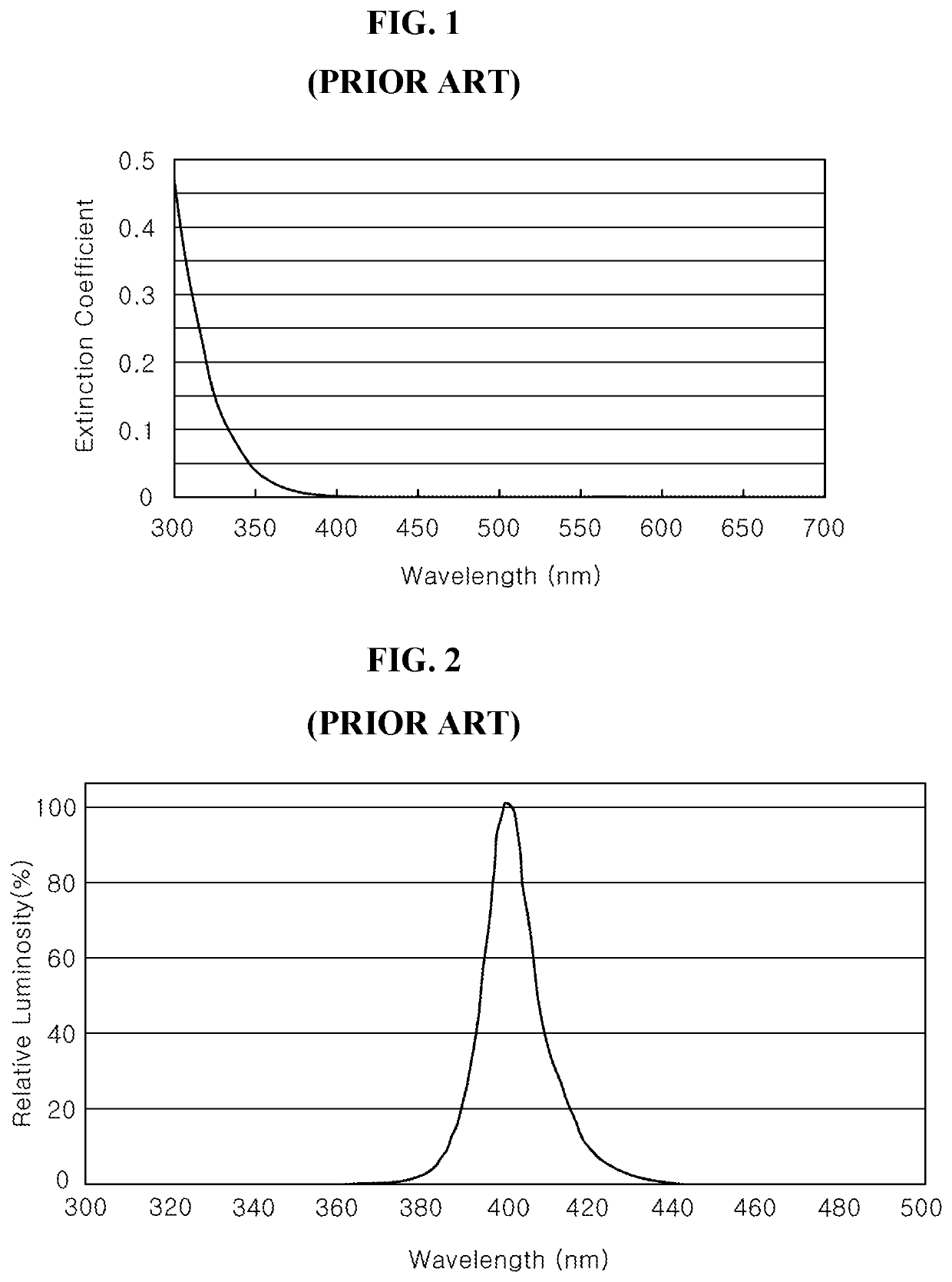
In this case, it is difficult to design the DBR suitable for the light emitting diode chip emitting visible light of short wavelength of about 440 nm or less, or near-ultraviolet light of shorter wavelength (about 300 nm to about 400 nm).
However, increasing the number of high refractive material layer increases light absorption, which may lower total reflectance.

Method used


Image

  • Light emitting diode chip having distributed bragg reflector
  • Light emitting diode chip having distributed bragg reflector
  • Light emitting diode chip having distributed bragg reflector

Examples


Embodiment Construction

[0056]In the following description, for the purposes of explanation, numerous specific details are set forth in order to provide a thorough understanding of various exemplary embodiments or implementations of the invention. As used herein “embodiments” and “implementations” are interchangeable words that are non-limiting examples of devices or methods employing one or more of the inventive concepts disclosed herein. It is apparent, however, that various exemplary embodiments may be practiced without these specific details or with one or more equivalent arrangements. In other instances, well-known structures and devices are shown in block diagram form in order to avoid unnecessarily obscuring various exemplary embodiments. Further, various exemplary embodiments may be different, but do not have to be exclusive. For example, specific shapes, configurations, and characteristics of an exemplary embodiment may be used or implemented in another exemplary embodiment without departing from ...


PUM


Abstract

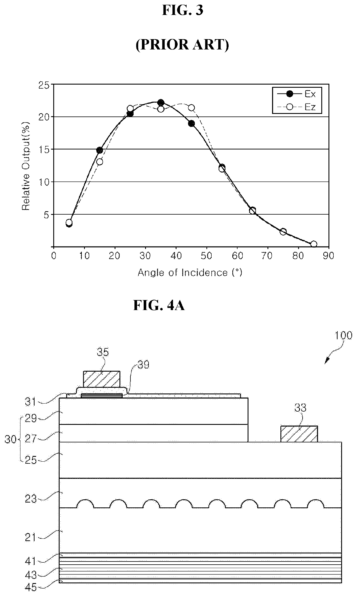
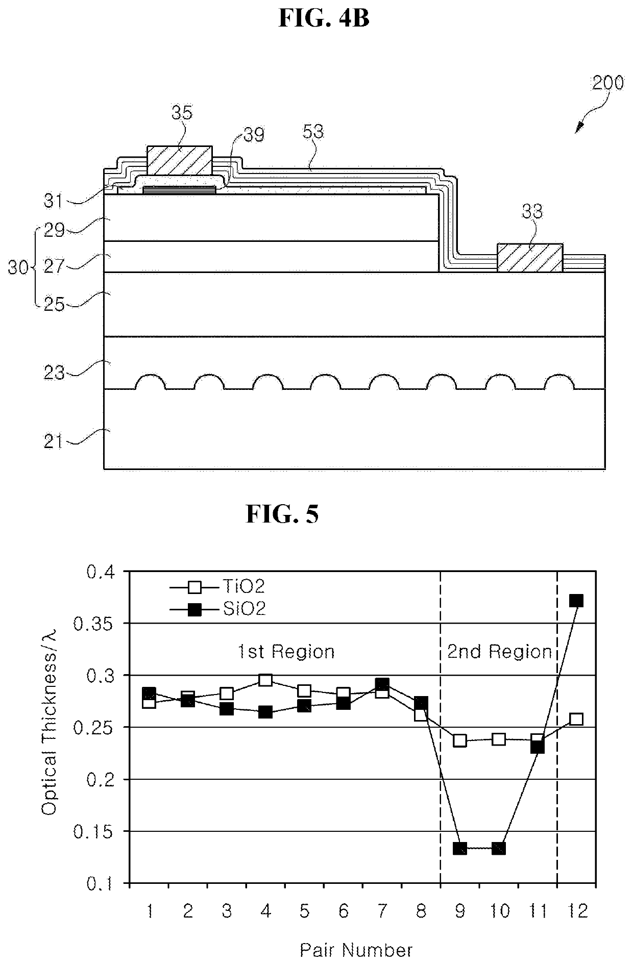
A light emitting diode chip including a light emitting structure and a distributed Bragg reflector (DBR) disposed thereon to reflect light, the DBR includes alternatively stacked first material layers having a low refractive index and second material layers having a high refractive index, and, with respect to a peak wavelength λ of light emitted, the DBR includes a first region having pairs of the first and second material layers each having an optical thickness greater than 0.25λ and less than 0.3λ, a last pair of the first and second material layers disposed farthest from the light emitting structure, and a second region between the first region and the last pair, each of the material layers in the second region has an optical thickness less than 0.25λ, and the first material layers have a greater optical thickness deviation than that of the second material layers in the second region.

Description

CROSS REFERENCE TO RELATED APPLICATION[0001]This application claims priority from and the benefit of Korean Patent Application No. 10-2018-0061744, filed on May 30, 2018, which is hereby incorporated by reference for all purposes as if fully set forth herein.BACKGROUNDField[0002]Exemplary embodiments of the invention relate generally to a light emitting diode chip and, more particularly, to a light emitting diode chip including a distributed Bragg reflector with improved light extraction efficiency.Discussion of the Background[0003]A GaN-based light emitting diode emitting blue light or UV light is used in various applications. In addition, various types of commercially available light emitting diode packages may emit mixed light, for example, white light, and be used as a backlight unit or general lighting.[0004]Since light output of a light emitting diode package generally depends on luminous efficacy of a light emitting diode chip, continuous attempts have been made to improve lu...

Claims


Application Information

Patent Timeline
IPC IPC(8): H01L33/10H01L33/32
CPCH01L33/32H01L33/10H01L33/46H01L33/20H01L33/60H01L33/50
Inventor KIM, YE SEULKIM, KYOUNG WAN
Owner SEOUL VIOSYS CO LTD
Learn More