
Mechanical Magnetic Proximity Sensor Device

a proximity sensor and magnetic field technology, applied in the direction of mechanical actuation of burglar alarms, instruments, pulse techniques, etc., can solve the problems of little, if any, work done developing purely mechanical sensors, and the mechanical components of such systems do not possess the ability to process or analyze more nuanced inputs

Active Publication Date: 2019-12-05
SPIDER SECURITY PROD
View PDF0 Cites 0 Cited by
  • Summary
  • Abstract
  • Description
  • Claims
  • Application Information

AI Technical Summary

Benefits of technology

The patent describes a device that detects when two objects are close enough to each other and closes electrical contacts to indicate their relative position. The device uses a spring to provide its response when it detects magnetic material or a change in magnetic permeability. Additionally, the device has a mechanism that can detect if an external magnetic force is introduced, which would cause the contacts to be separated and trigger a signal. This helps to prevent the device from being tampered with and ensures its accuracy in detecting object proximity.

Problems solved by technology

Little, if any, work has been done developing purely mechanical sensors that provide an interface with the physical world and even less work has been done developing mechanical sensors where the analysis is performed by mechanical means, not electronic.
However, the mechanical components of such systems do not possess any ability process or analyze more nuanced inputs.
However, this type of system does not process nor communicate with components outside of its self-contained structure, thus allowing a self-contained system that minimizes the risk of outside interference or tampering attempts.
And, in many cases, the ability to reject extraneous inputs is also of great importance, especially when said external, extraneous input may be attributed to error or intentional tampering.
And, any such limit switch requires physical contact between the door and the limit switch, leaving the system vulnerable to malfunction because of the environment or because of normal wear and tear and any such limit switch is particularly vulnerable to tampering.
Once again, limit switches frequently malfunction because of normal wear and tear or contamination from the operating environment.
In many applications, electronic sensors are too prone to external interference or vulnerable to tampering, now called ‘hacking’ or ‘spoofing’.
For a two-wire system, electronic sensors may be prohibitively expensive.

Method used


Image

  • Mechanical Magnetic Proximity Sensor Device
  • Mechanical Magnetic Proximity Sensor Device
  • Mechanical Magnetic Proximity Sensor Device

Examples


Embodiment Construction

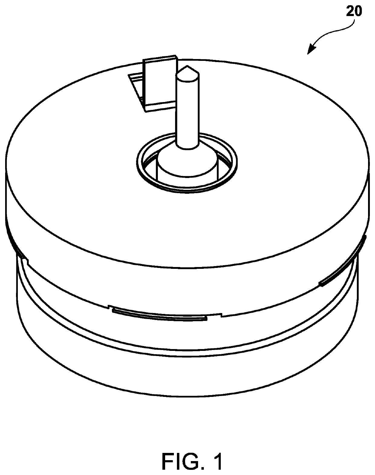
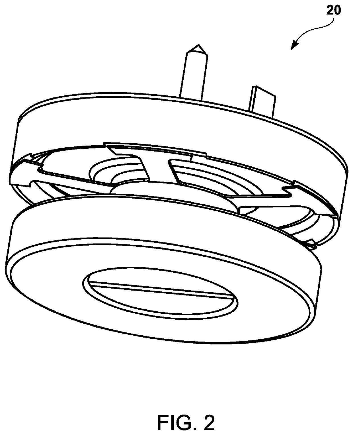
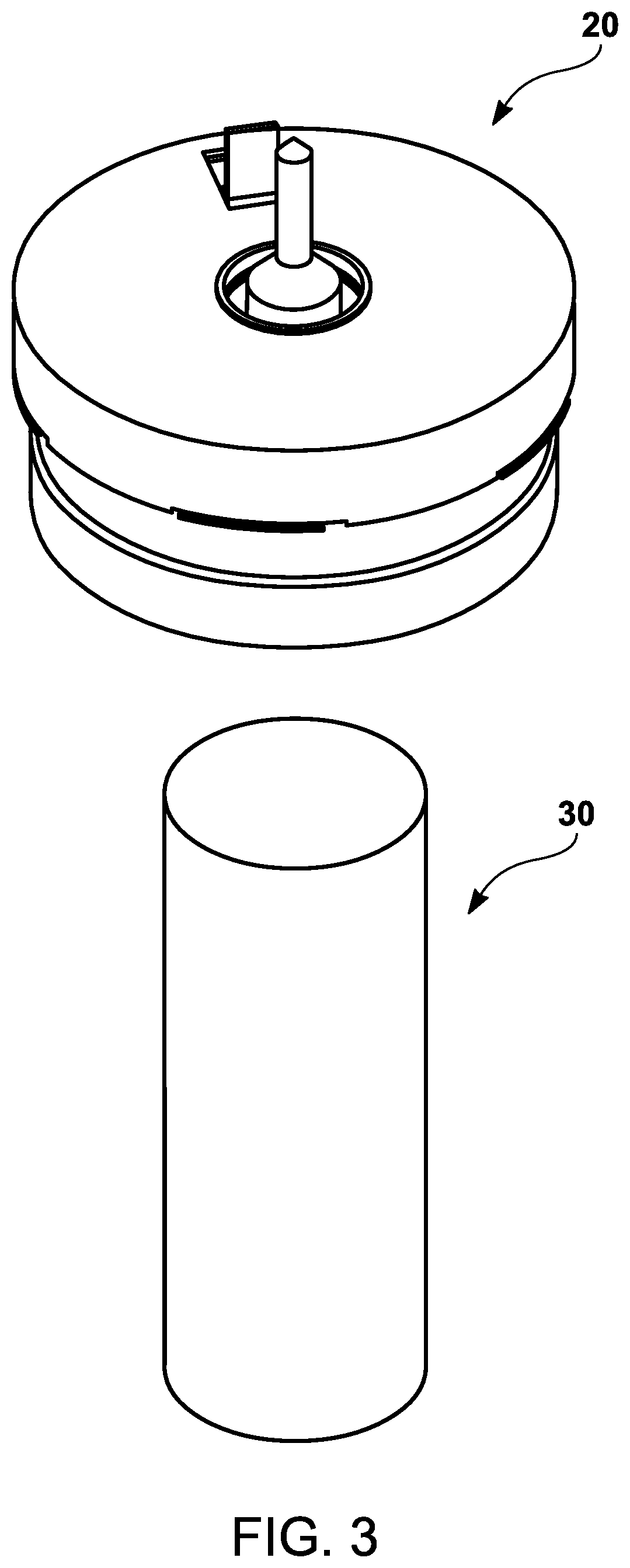
[0055]A mechanical proximity sensor assembly 20 as shown in FIG. 1 and FIG. 2. The sensor can sense or detect the relative position of two magnetic objects (the sensor 20 and the magnetic piece 30) as shown in FIG. 3. To further clarify, this mechanical magnetic proximity sensor can sense or detect an object in proximity to the sensor 20; thereby, establishing the relative position of the magnetic piece 30 to the sensor 20.

[0056]The detection envelope is defined as a three-dimensional magnetic field and can be described in a standard coordinate system composed of the X-Y plane and the Z axis perpendicular to the X-Y plane, as shown in FIG. 4. Any magnetic piece 30 within the detection envelope will cause the sensor to close a set of electro-mechanical contacts, permitting electrical current to flow in an external circuit.

[0057]The shape of the detection envelope is that of a truncated cone, as shown in FIGS. 5A and 5B. The shape of the cone is determined or set by the internal compo...


PUM


Abstract

A sensor, comprised of various mechanical components and electromechanical components, that measures / detects the relative position between two (2) or more objects and can measure / detect relative acceleration of one (1) or more objects, using fundamental natural physical forces, e.g. magnetism, electrostatics. More particularly, this invention relates to a sensor that can measure / detect the relative position of two or more objects and / or measure / detect the acceleration of one or more objects. Specifically, this invention uses fundamental physical forces in combination with mechanical components to actuate electro-optical-mechanical signal devices, e.g. electrical switches, optical switches, magnetic switches.

Description

CROSS REFERENCE TO RELATED APPLICATIONS[0001]This Application claims priority to U.S. Provisional Patent Application No. 62 / 679,351 filed on Jun. 1, 2018.STATEMENT REGARDING FEDERALLY SPONSORED RESEARCH AND DEVELOPMENT[0002]None.FIELD OF THE INVENTION[0003]The present invention relates to a mechanical magnetic proximity sensor device, comprised of various mechanical components and electromechanical components, that measures / detects the relative position between two or more objects and can measure / detect relative acceleration of one or more objects, using fundamental natural physical forces, e.g. magnetism, electrostatics.BACKGROUND OF THE INVENTION[0004]The current state-of-the-art of proximity sensor is almost exclusively solid state or electronic. Little, if any, work has been done developing purely mechanical sensors that provide an interface with the physical world and even less work has been done developing mechanical sensors where the analysis is performed by mechanical means,...

Claims


Application Information

Patent Timeline
IPC IPC(8): G01B7/14
CPCG01B7/14H03K17/97H03K2217/9658G01P15/105G01D5/145G08B13/08G08B29/046
Inventor BUENAVENTURA, BRYAN
Owner SPIDER SECURITY PROD
Learn More