
Vehicle seat

a technology for reclining chairs and seats, applied in the field of reclining seats, can solve the problems of increasing affecting the comfort of the seat, and the lower end of the paired support members to be displaced in directions away from each other, so as to reduce the weight of the vehicle seat, reduce the deformation of the paired support members, and reduce the weight

Active Publication Date: 2019-11-28
TOYOTA BOSHOKU KK
View PDF0 Cites 1 Cited by
  • Summary
  • Abstract
  • Description
  • Claims
  • Application Information

AI Technical Summary

Benefits of technology

The technical effect of this patent is to create a car seat where the support member is less likely to deform and the seat is lighter.

Problems solved by technology

This deformation often occurs when the paired support members disposed to face each other in a seat width direction experience buckling, causing the lower ends of the paired support members to be displaced in directions away from each other.
As a result, breakage may occur at joints between the recliner and the paired support members.
Employing these configurations, however, inevitably increases the weight of the vehicle seat, resulting in failure to achieve weight reduction of the vehicle seat.

Method used


Image

  • Vehicle seat
  • Vehicle seat
  • Vehicle seat

Examples


first embodiment

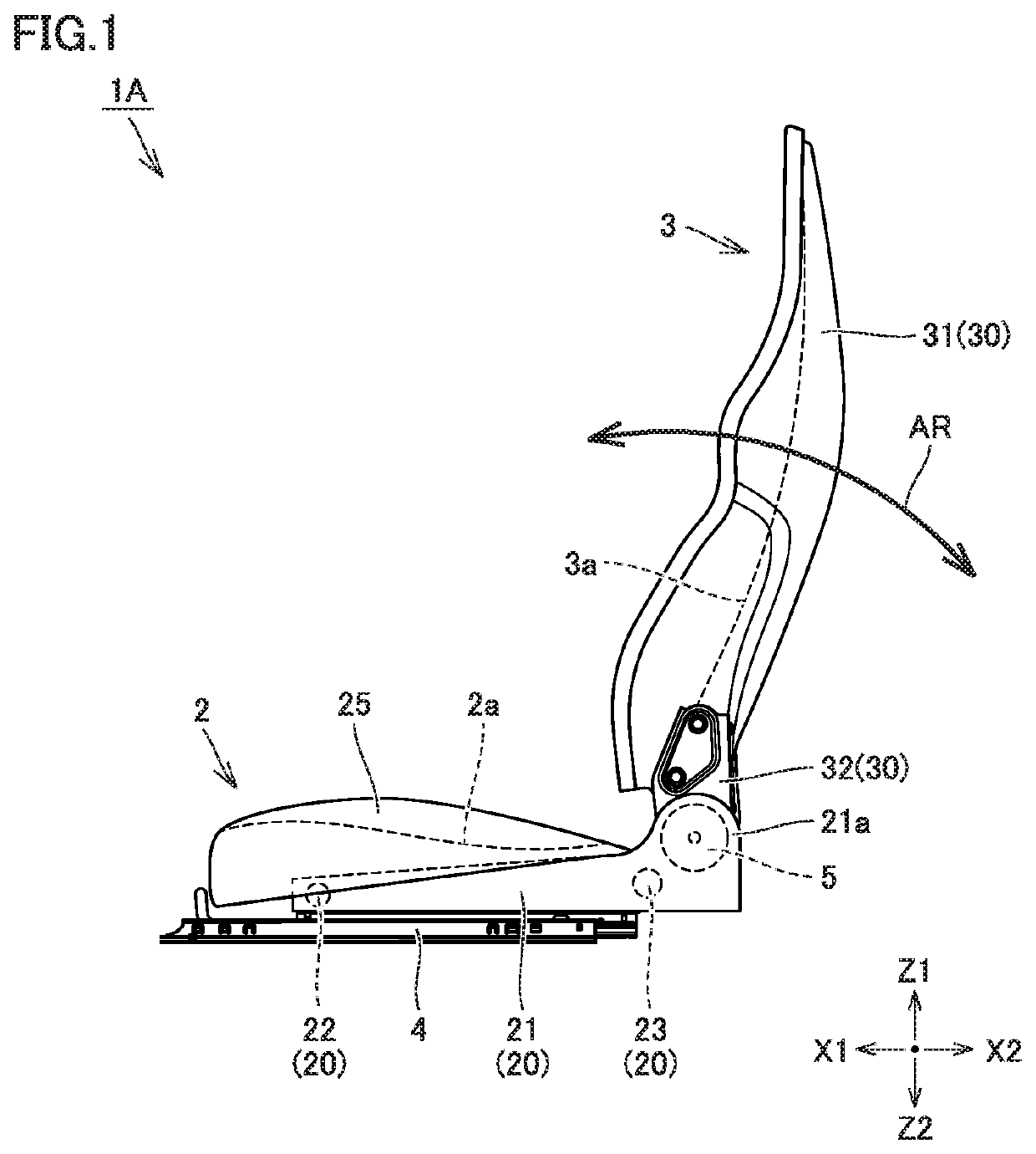
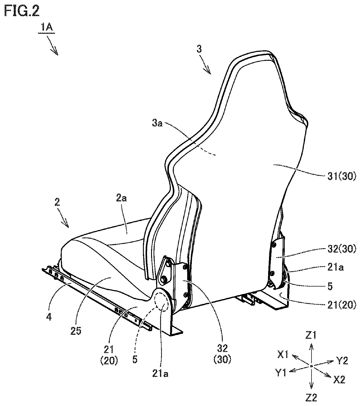
[0022]FIGS. 1 and 2 are a schematic side view and a schematic perspective view of a vehicle seat according to a first embodiment, respectively. First, a schematic configuration of a vehicle seat 1A according to the present embodiment is described with reference to FIGS. 1 and 2.

[0023]As shown in FIGS. 1 and 2, vehicle seat 1A is installed on the vehicle's floor via a sliding mechanism 4, for example. Vehicle seat 1A mainly includes a seat cushion 2, a seat back 3, and a recliner 5.

[0024]Seat cushion 2 has a sitting surface 2a on its upper surface, on which the occupant can sit. Seat cushion 2 is disposed such that sitting surface 2a is substantially parallel to the vehicle's floor. Seat back 3 has a backrest surface 3a on its front surface, against which the occupant can rest its back. Seat back 3 is disposed to rise from the rear end of seat cushion 2.

[0025]Seat cushion 2 has a cushion frame 20, a cushion pad 25 covering cushion frame 20, and a cushion cover (not shown) covering cu...

second embodiment

[0075]FIG. 10 is a schematic perspective view in the vicinity of the upper arm of a vehicle seat according, to a second embodiment. A vehicle seat 1B according to the present embodiment is described below with reference to FIG. 10.

[0076]As shown in FIG. 10, vehicle seat 1B according to the present embodiment is different in the shape of upper arm 32 serving as a support member, as compared to vehicle seat 1A according to the first embodiment described above.

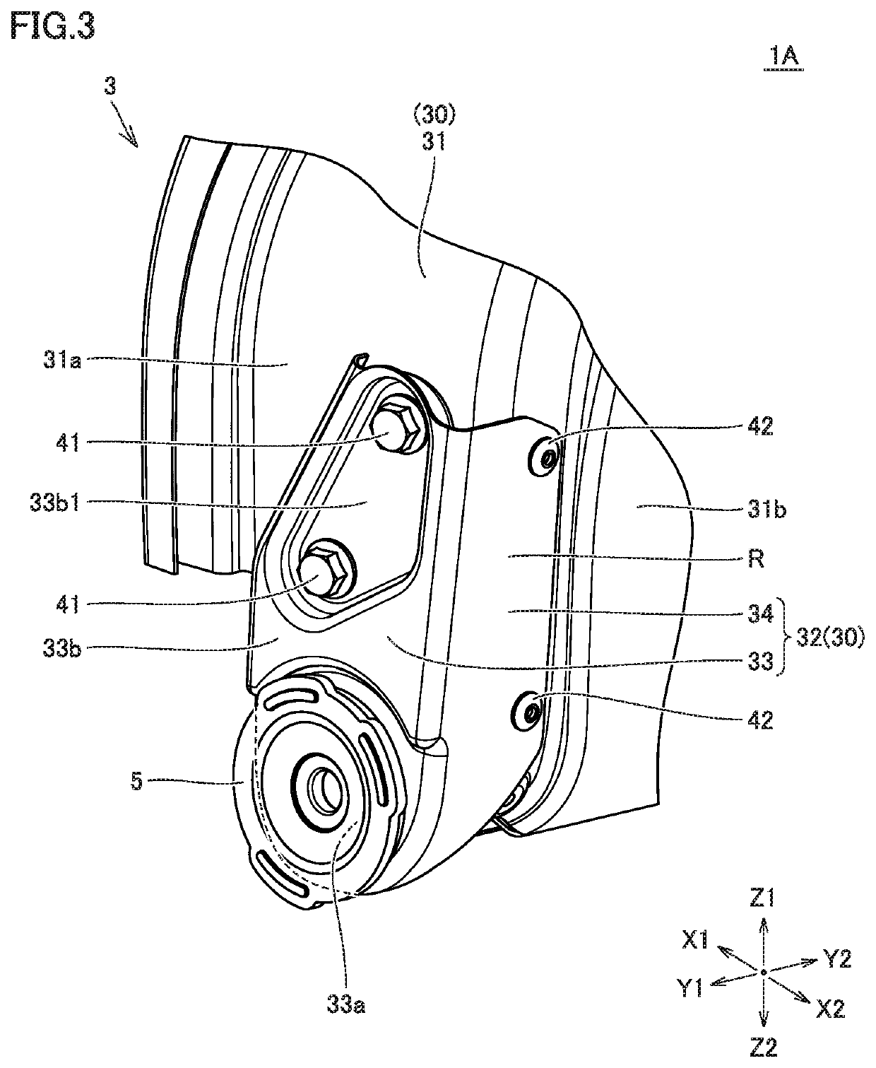
[0077]Specifically, in vehicle seat 1A according to the first embodiment described above, rear plate portion 34 has a configuration provided to rise from the entire rear end of side plate portion 33, whereas in vehicle seat 1B according to the present embodiment, rear plate portion 34 has a configuration provided to rise only from the lower position of the rear end of side plate portion 33. As a result, in the present embodiment, rear plate portion 34 only has region R described above. Rear plate portion 34 is not provided to ris...


PUM


Abstract

A vehicle seat includes a back frame mounted on a cushion frame is a recliner in a pivotally movable manner. The back frame has a support member connected to the recliner, and a seat back shell supported by the support member. The support member has a side plate portion and a rear plate portion facing a side surface and a rear surface of the seat back shell, respectively, and the side plate portion has a base portion fixed to the recliner, and an extension portion provided to extend more upward than the base portion. The side plate portion is fixed at the extension portion to the side surface of the seat back shell, and the rear plate portion is at least fixed in a region to the rear surface of the seat back shell, the region provided to rise from a lower position of the side plate portion.

Description

[0001]This nonprovisional application is based on Japanese Patent Application No. 2018-097774 filed on May 22, 2018 with the Japan Patent Office, the entire contents of which are hereby incorporated by reference.BACKGROUNDField[0002]The present disclosure relates to vehicle seats, and more particularly to a vehicle seat installed in a vehicle such as an automobile.Description of the Background Art[0003]A seat back commonly referred to as a shell type seat back is known as a seat back provided for a vehicle seat. In the shell type seat back, a back frame forming its framework is formed of a thin plate-like seat back shell made of a composite resin material, a metal material or the like. As a result, an improved tit is provided when an occupant rests its back against the seat back as compared to a seat back having a common configuration.[0004]Japanese National Patent Publication No. 2007-506598, for example, discloses a vehicle seat including this type of seat back. In the vehicle sea...

Claims


Application Information

Patent Timeline
Patent Type & Authority Applications(United States)
IPC IPC(8): B60N2/42B60N2/68B60N2/20
CPCB60N2/20B60N2/4249B60N2/686B60N2/4228B60N2/2356B60N2/68B60N2/682
Inventor WATANABE, HIROFUMIMIZOBATA, HIROSHIKATO, YASUHIRO
Owner TOYOTA BOSHOKU KK
Learn More