Superconducting resonating cavity with laser welded seam and method of formation thereof

a superconducting radio frequency and laser welding technology, applied in the direction of waveguide type devices, welding/soldering/cutting articles, manufacturing tools, etc., can solve the problems of superconducting interior surface performance limits, x-ray production, and cavity heating, etc., to achieve better treatment of inner surface

Active Publication Date: 2019-11-21
II VI DELAWARE INC
View PDF6 Cites 0 Cited by
  • Summary
  • Abstract
  • Description
  • Claims
  • Application Information

AI Technical Summary

Benefits of technology

This patent describes a way to make niobium cells used for superconducting radio frequencies. The method involves relocating weld seams to less critical areas on the inside surface of the cell. This change allows for better treatment of the cell's equator, which is important for its performance.

Problems solved by technology

However, higher gradients require higher internal fields, pushing the performance limits for the superconducting interior surfaces.
High voltages along the interior of the cavity can cause electrons to be emitted from the surface, producing X-rays and heating the cavity.
Moreover, variations in the surface can increase the amount of magnetic field to which the surface of the cavity is exposed, leading to a premature quench.
Surface roughness in areas of high magnetic field can cause an enhancement of the local magnetic field to a level beyond the critical value of the niobium which can lead to a breakdown in the superconducting state.
Surface roughness in areas of high electric field can cause field emission, heating the surface and causing a breakdown in the superconducting state.
The limitations of Q0 and accelerating gradient are largely due to exceeding the critical magnetic field at the equator of the cavity.
This process, while well studied and controlled, still gives inconsistent results.
Post-processing of the surface is limited to “grinder-on-a-stick” and “camera-on-a-stick” inspection before chemical etching of the weld.

Method used


Image

  • Superconducting resonating cavity with laser welded seam and method of formation thereof
  • Superconducting resonating cavity with laser welded seam and method of formation thereof
  • Superconducting resonating cavity with laser welded seam and method of formation thereof

Examples


Embodiment Construction

[0034]Various non-limiting examples will now be described with reference to the accompanying figures where like reference numbers correspond to like or functionally equivalent elements.

[0035]For purposes of the description hereinafter, the terms “end,”“upper,”“lower,”“right,”“left,”“vertical,”“horizontal,”“top,”“bottom,”“lateral,”“longitudinal,” and derivatives thereof shall relate to the example(s) as oriented in the drawing figures. However, it is to be understood that the example(s) may assume various alternative variations and step sequences, except where expressly specified to the contrary. It is also to be understood that the specific example(s) illustrated in the attached drawings, and described in the following specification, are simply exemplary examples or aspects of the invention. Hence, the specific examples or aspects disclosed herein are not to be construed as limiting.

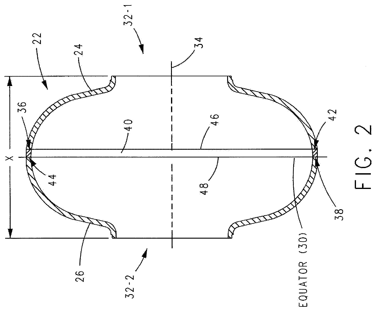
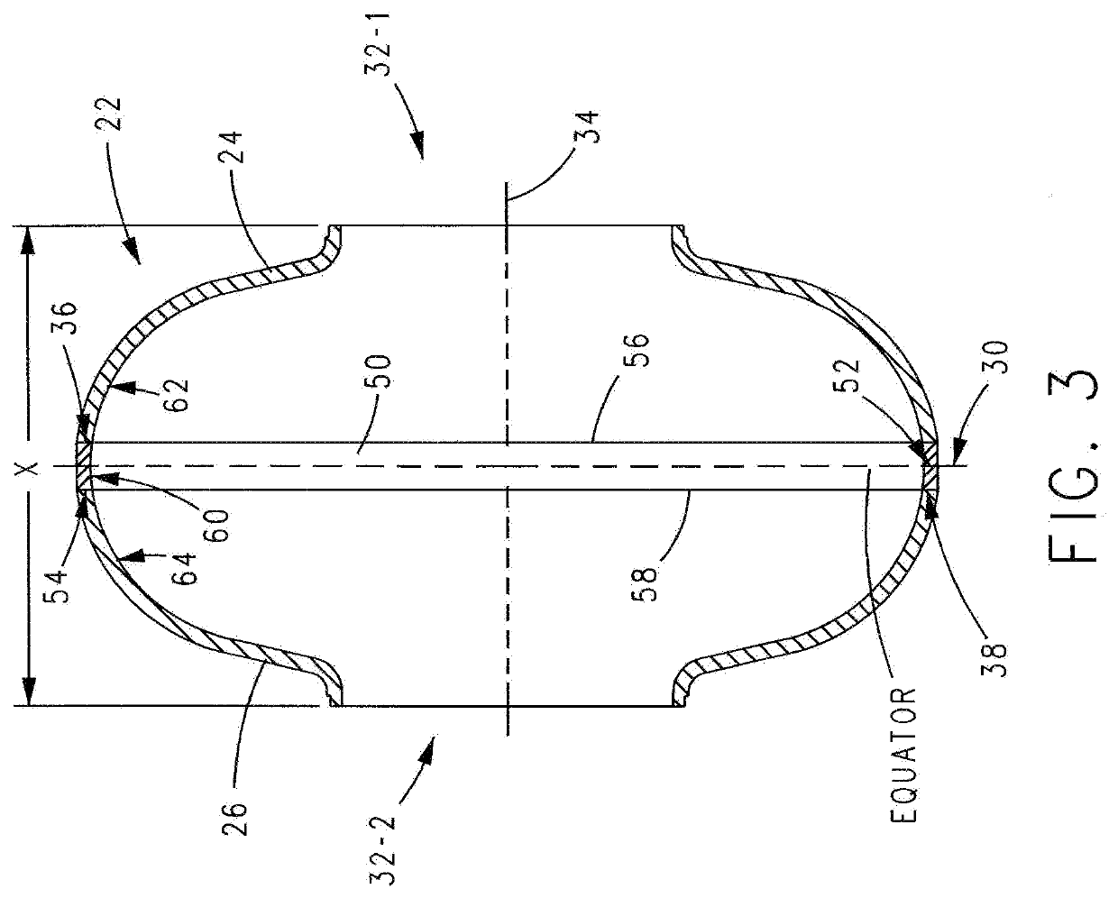
[0036]The Background having thus described a prior art cell 4 and a SRF cavity 2 where one or a numbe...


PUM

PropertyMeasurementUnit
latitudeaaaaaaaaaa
widthaaaaaaaaaa
widthaaaaaaaaaa

Abstract

A superconducting radio frequency cell includes a body defining a hollow cavity having a first iris and second iris at opposite ends of the body, an axis that extends between the first and second irises, and an equator around the axis between the first and second irises. The body includes at least a first weld seam around the axis at a location on the body spaced from the equator. Each weld seam extends through the body and has opposite sides terminating proximate an interior and an exterior of the body, and each weld seam includes a first, conduction weld formed on one side of the weld seam and a second weld formed on the opposite side of the weld seam. The second weld can be a conduction weld, a keyhole weld, or a transition weld.

Description

CROSS-REFERENCE TO RELATED APPLICATION[0001]This application is a continuation-in-part of U.S. patent application Ser. No. 15 / 983,340, filed May 18, 2018, titled “Superconducting Resonating Cavity and Method of Production Thereof”.BACKGROUND OF THE INVENTIONField of the Invention[0002]The present invention relates to superconducting radio frequency (SRF) cells, methods of producing SRF cells, a weld seam that can be used with an SRF cell or other objects, and a method of forming the weld seam.Description of Related Art[0003]RF cavities are used to accelerate groups of charged particles towards a target. For many applications, the benefits of using cavities with superconducting internal surfaces outweigh the increased costs associated with cooling the cavities to cryogenic temperatures. The cavities are judged by their quality factor and acceleration gradient. Quality factor (Q0) gives the inverse of the amount of energy lost in each cycle of the system. High quality factors reduce o...

Claims


Application Information

Patent Timeline
Patent Type & Authority Applications(United States)
IPC IPC(8): H01P7/06H05H7/20H01P11/00B23K26/282
CPCH01P11/008B23K26/282H01P7/06H05H7/20B23K2101/36B23K2103/50B23K26/28
Inventor HEDGES, ALANBRANIGAN, KYLE
Owner II VI DELAWARE INC
Why Eureka
Try Eureka