Radial flow runner for a hydraulic machine

Inactive Publication Date: 2019-11-14
VOITH PATENT GMBH
View PDF0 Cites 0 Cited by
  • Summary
  • Abstract
  • Description
  • Claims
  • Application Information

AI Technical Summary

Benefits of technology

The patent is about a device called a runner that reduces drag and improves hydraulic efficiency by allowing water to leak out of its blades. This helps the device rotate more smoothly and reduces the amount of force needed to move it.

Problems solved by technology

Hydraulic machines including a radial flow runner of the Francis type are suffering from axial thrust applied to the runner of the hydraulic machine.
Since the sealing between the runner and the high pressure side of the water passage cannot be made perfectly tight, water can get in the space between the head cover of the hydraulic machine and the runner crown resulting in a high axial thrust.
Balancing pipes are generally expensive.
The effectiveness of the prior art balancing holes depends on the revolution speed of the runner and the blade geometry and therefore leading not always to satisfactory results concerning thrust reduction.
Especially in the case of modernization projects when an existing runner relying on balancing holes has to be replaced by a new runner the situation can occur that the modern blade geometry cannot be accommodated by balancing holes of the known type and the installation of balancing pipes is impractical since the existing hydraulic machine is embedded in concrete.
This geometry provides improved performance characteristics but in many cases makes the use of balancing holes in the runner crown less effective at reducing thrust due to radial pumping effects within the runner crown space below the shaft flange.
In some cases where the flange connecting the runner to the shaft is at a relatively low elevation, there may no longer be sufficient space available in the runner crown flange to accommodate balancing holes of the known type and so an alternative solution for thrust reduction is necessary.

Method used


Image

  • Radial flow runner for a hydraulic machine
  • Radial flow runner for a hydraulic machine
  • Radial flow runner for a hydraulic machine

Examples


Embodiment Construction

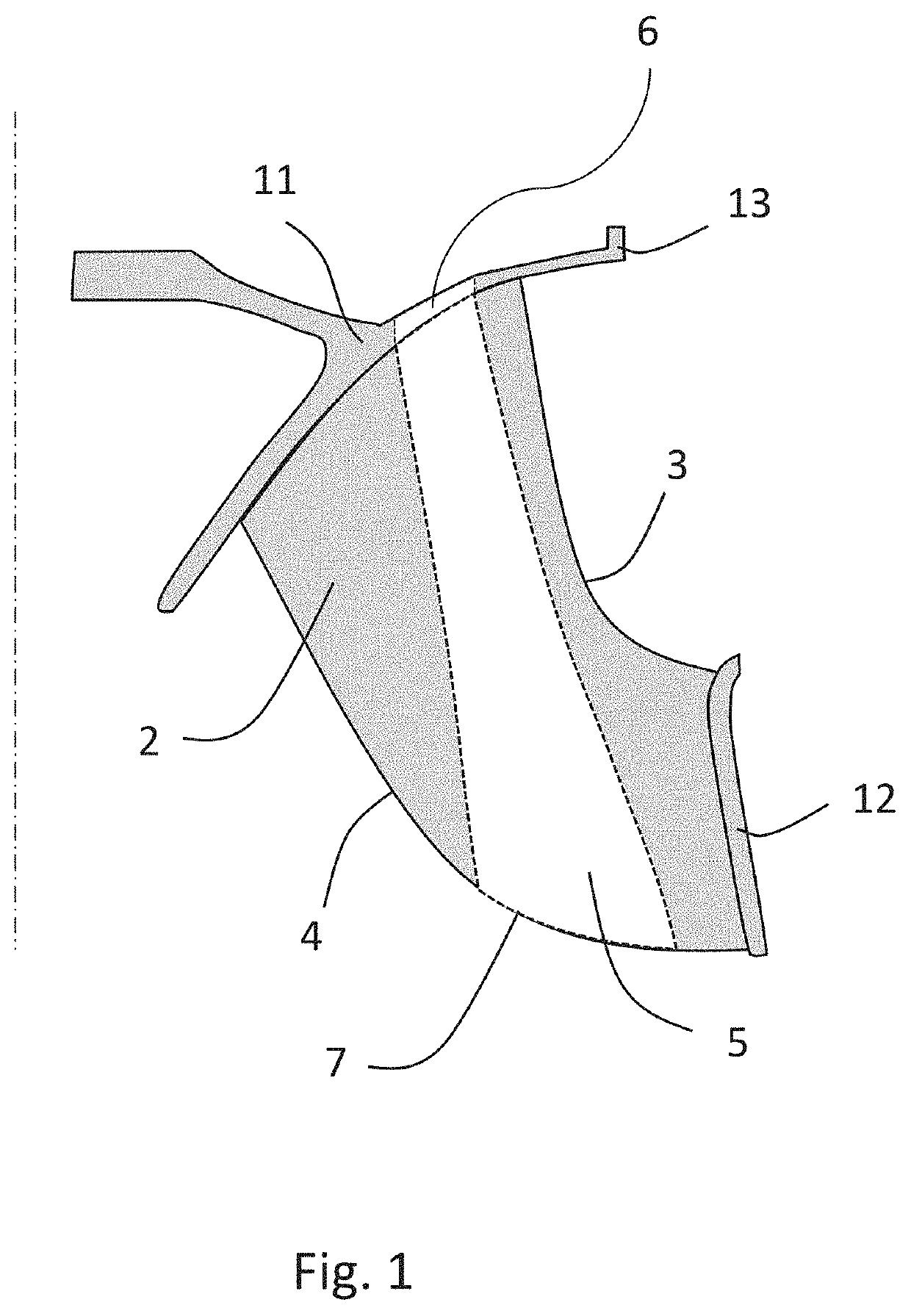
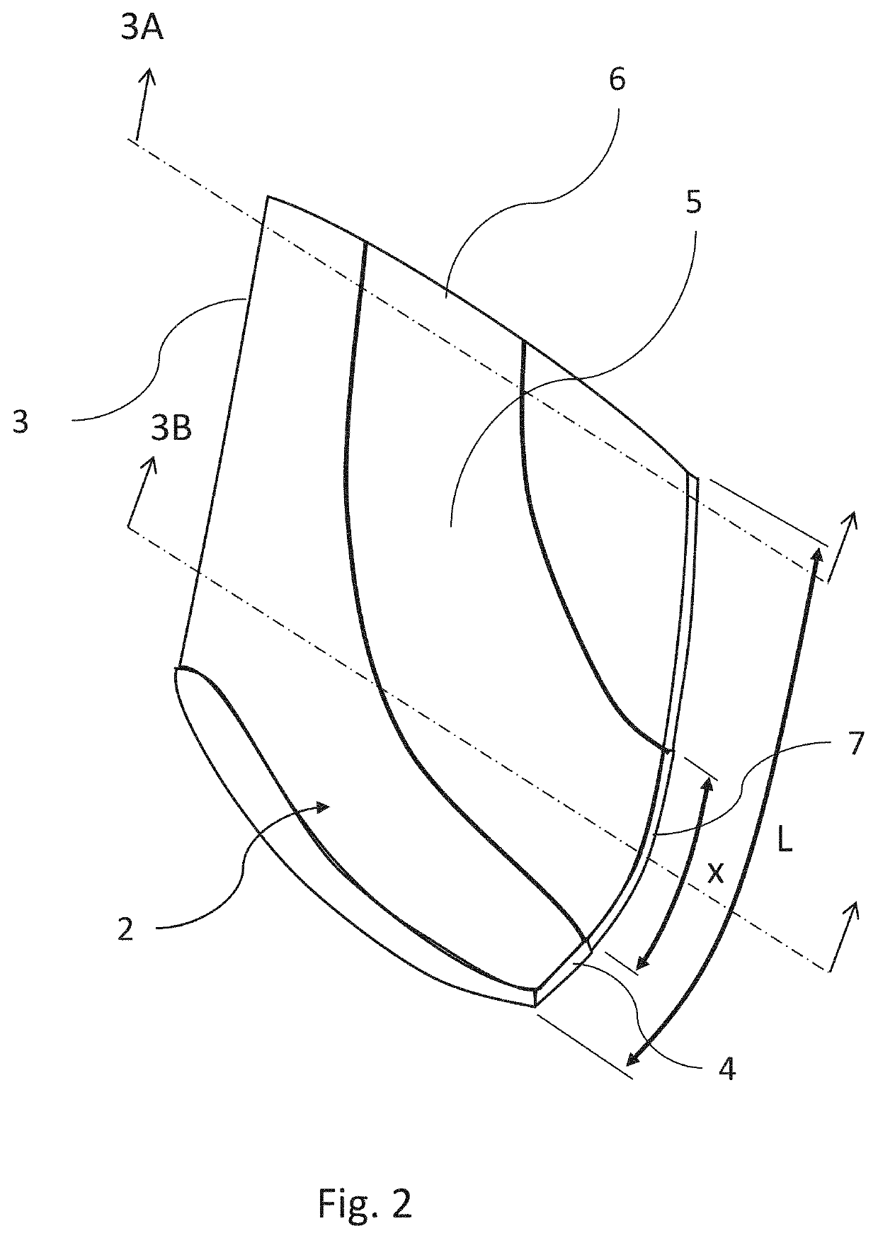
[0016]FIG. 1 displays schematically a cross-sectional view of a Francis turbine runner according to the present invention. The runner crown is designated as 11. A runner blade 2 extends between the crown 11 and the band designated as 12. The blade 2 has two edges designate by 3 and 4. The fluid entering the runner flows from edge 3 towards edge 4, whereas the high pressure side adjoins to edge 3 and the low pressure side adjoins to edge 4. It is clear that in pumping mode the flow direction of the fluid is reversed. The runner crown 11 includes circumferential located seal 13 designated as 13. Seal 13 are construed to seal the space above crown 11 against high pressure water. However due to the imperfection of the sealing a small amount of high pressure water will be present in the space above the runner crown 11 leading to the undesired axial thrust. The runner crown 11 includes an inlet aperture designated by 6. The inlet aperture 6 is located in a portion of the crown, which is e...


PUM


Abstract

A runner of the Francis type including a crown, a plurality of blades, each blade being defined by a pressure surface, a suction surface, an edge adjoining the high pressure side and a spaced apart edge adjoining the low pressure side. The crown includes a seal to seal the space above the crown against water from the high pressure side. The further runner includes at least one passage being capable to drain high pressure leakage water to the low pressure side. The passage includes an inlet aperture located in a portion of the crown which is exposed to high pressure leakage water. The passage is located within a blade and leads from the inlet aperture to the edge of the same blade adjoining to the low pressure side. The passage is shaped to form a continuous opening in the same edge adjoining to the low pressure side.

Description

CROSS REFERENCE TO RELATED APPLICATIONS[0001]This is a continuation of PCT application No. PCT / EP2017 / 081659, entitled “RADIAL FLOW RUNNER FOR A HYDRAULIC MACHINE”, filed Dec. 6, 2017, which is incorporated herein by reference.BACKGROUND OF THE INVENTION1. Field of the Invention[0002]The present invention relates generally to hydroelectric turbine or pump installations with a radial flow runner of the Francis type.2. Description of the Related Art[0003]Hydraulic machines including a radial flow runner of the Francis type are suffering from axial thrust applied to the runner of the hydraulic machine. Since the sealing between the runner and the high pressure side of the water passage cannot be made perfectly tight, water can get in the space between the head cover of the hydraulic machine and the runner crown resulting in a high axial thrust. To reduce the axial thrust prior art has proposed several concepts. One concept comprises balancing pipes draining the water passing the seals ...

Claims


Application Information

Patent Timeline
IPC IPC(8): F04D29/18F04D3/00F04D29/00F04D29/08F04D29/40F04D29/52F04D29/54
CPCF04D29/406F04D29/007F04D29/548F04D29/086F04D3/00F04D29/181F04D29/528F03B3/02F03B11/006Y02E10/20
Inventor COULSON, STUARTDUNBAR, KENNETHKOTZMAN, BENJAMINSEIFARTH, JOHNMC GINNIS, DANIEL
Owner VOITH PATENT GMBH
Why Eureka
Try Eureka