
Method for the production of a syngas from a stream of light hydrocarbons and from combustion fumes from a cement clinker production unit

a technology of light hydrocarbons and combustion fumes, which is applied in cement production, clinker production, manufacturing tools, etc., can solve the problems of not being very high, not satisfactory hsub>2/sub>/co ratio of syngas produced during dry reforming or steam methane reforming, and not satisfying,

Inactive Publication Date: 2019-11-14
INST FR DU PETROLE +1
View PDF0 Cites 1 Cited by
  • Summary
  • Abstract
  • Description
  • Claims
  • Application Information

AI Technical Summary

Benefits of technology

The present invention relates to a process for producing syngas containing CO and H2 from a stream of light hydrocarbons and combustion flue gases from a cement clinker production unit. The process involves collecting the combustion flue gases from the cement clinker production unit and optionally treating them to obtain treated combustion flue gases. A reaction stream is then prepared by combining the light hydrocarbons and the treated combustion flue gases. The reaction stream is sent to a tri-reforming reactor and operated at a temperature of between 650 and 900°C, a pressure of between 0.1 and 5 MPa, and an HSV of between 0.1 and 200 Nm3 / h. The technical effects of the invention include the ability to produce syngas with a high H2 / CO volume ratio and a low CO2 content, and the use of a supported catalyst containing an active phase comprising at least one metal element in oxide form or in metal form.

Problems solved by technology

However, the H2 / CO ratios of the syngas produced during dry reforming or steam methane reforming are not satisfactory for the production of fuels which require an H2 / CO molar ratio of about 2.
The combination of these two processes makes it possible to obtain ratios closer to those desired, but the resulting production of carbon (“coke”) on the catalyst is a major drawback.
However, the combustion gases are taken at the outlet of kiln chimneys, and therefore have a temperature that is not very high, i.e. Approximately 150° C.
Consequently, it is necessary to reheat the combustion gases to the tri-reforming reaction temperature, i.e. a temperature typically of between 650 and 900° C. Moreover, the relatively low temperature of the combustion gases at the chimney outlet can lead to the condensation of steam contained in the combustion gases and therefore can substantially modify the H2O / Hydrocarbon (HC) ratio, which would no longer be optimal for the catalytic tri-reforming reaction.

Method used


Image

  • Method for the production of a syngas from a stream of light hydrocarbons and from combustion fumes from a cement clinker production unit
  • Method for the production of a syngas from a stream of light hydrocarbons and from combustion fumes from a cement clinker production unit

Examples


example 1

Conversion of a Cement Works Effluent into a Gas Composition Comprising Carbon Monoxide and Dihydrogen (in Accordance with the Invention)

[0112]The combustion flue gases from the clinker production are collected at the level of the multi-cyclone preheater of the clinker production unit, upstream of the chimney for discharging the combustion flue gases. The combustion flue gases collected comprise 25% by volume of CO2, 12.5% by volume of H2O, 3% by volume of O2 and 59% by volume of N2. The temperature of the combustion flue gases collected is 450° C. Provisions of steam and of oxygen (by adding atmospheric air), and also a flow of natural gas, are added to these combustion flue gases in order to obtain the following volume ratios:

N2 / HC=1.05;

H2O / HC=0.33;

CO2 / HC=0.25;

O2 / HC=0.15.

[0113]The reaction stream is brought to 850° C. under a pressure of 0.25 MPa (2.5 bar), in the presence of a nickel-based catalyst (HiFUEL R110, Johnson Matthey Plc, Alfa Aesar). The hourly space velocity of the r...

example 2

Conversion of a Cement Works Effluent into a Gas Composition Comprising Carbon Monoxide and Dihydrogen (in Accordance with the Invention)

[0117]The combustion flue gases from the clinker production are collected at the level of the multi-cyclone preheater of the clinker production unit, upstream of the chimney for discharging the combustion flue gases. The combustion flue gases collected comprise 25% by volume of CO2, 12.5% by volume of H2O, 3% by volume of O2 and 59% by volume of N2. The temperature of the combustion flue gases collected is 450° C. Provisions of steam and of oxygen (by adding atmospheric air), and also a flow of natural gas, are added to these combustion flue gases in order to obtain the following volume ratios:

N2 / HC=0.98;

H2O / HC=0.66;

CO2 / HC=0.32;

O2 / HC=0.10.

[0118]The reaction stream is brought to 850° C. under a pressure of 0.25 MPa (2.5 bar), in the presence of a nickel-based catalyst (HiFUEL® R110, Johnson Matthey Plc, Alfa Aesar). The hourly space velocity of the ...


PUM

PropertyMeasurementUnit
pressureaaaaaaaaaa
pressureaaaaaaaaaa
temperatureaaaaaaaaaa

Abstract

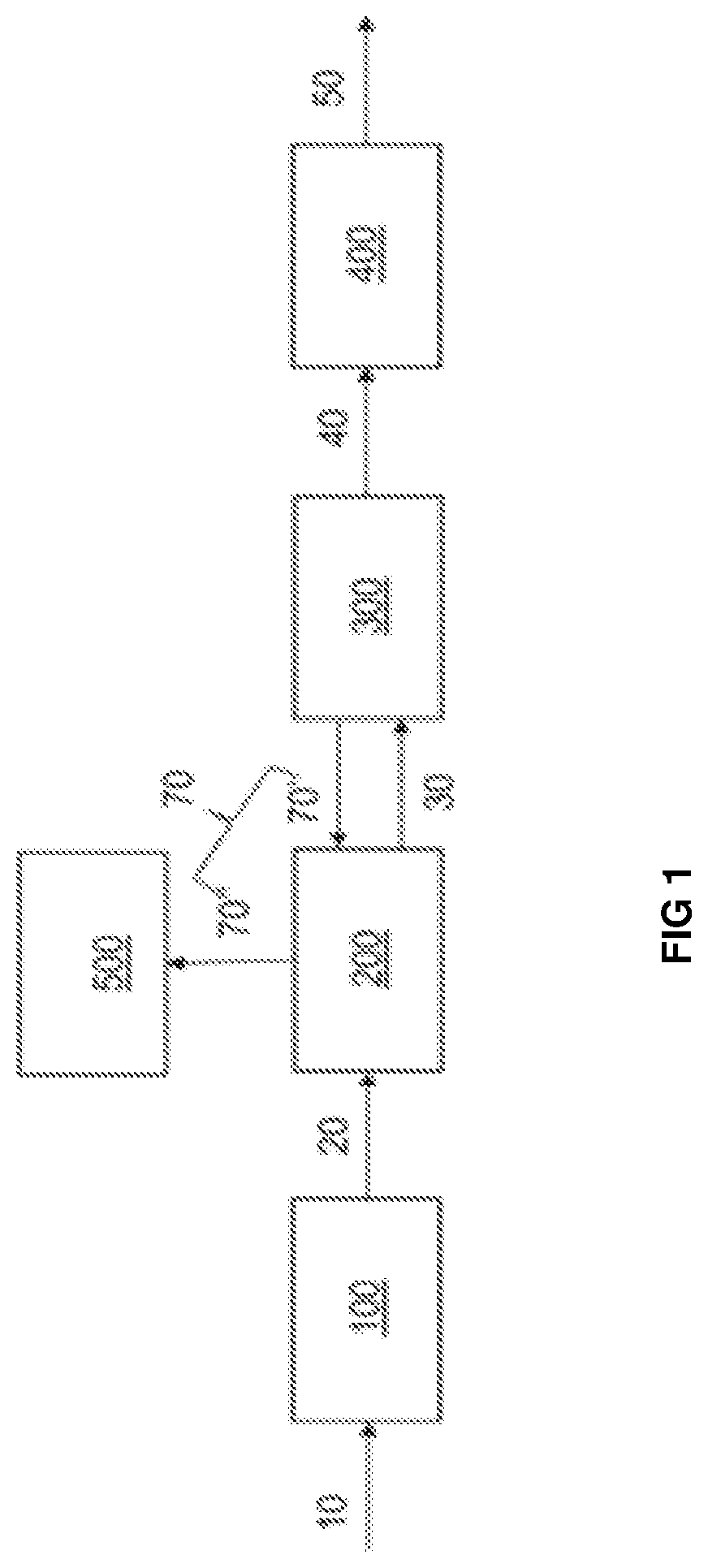
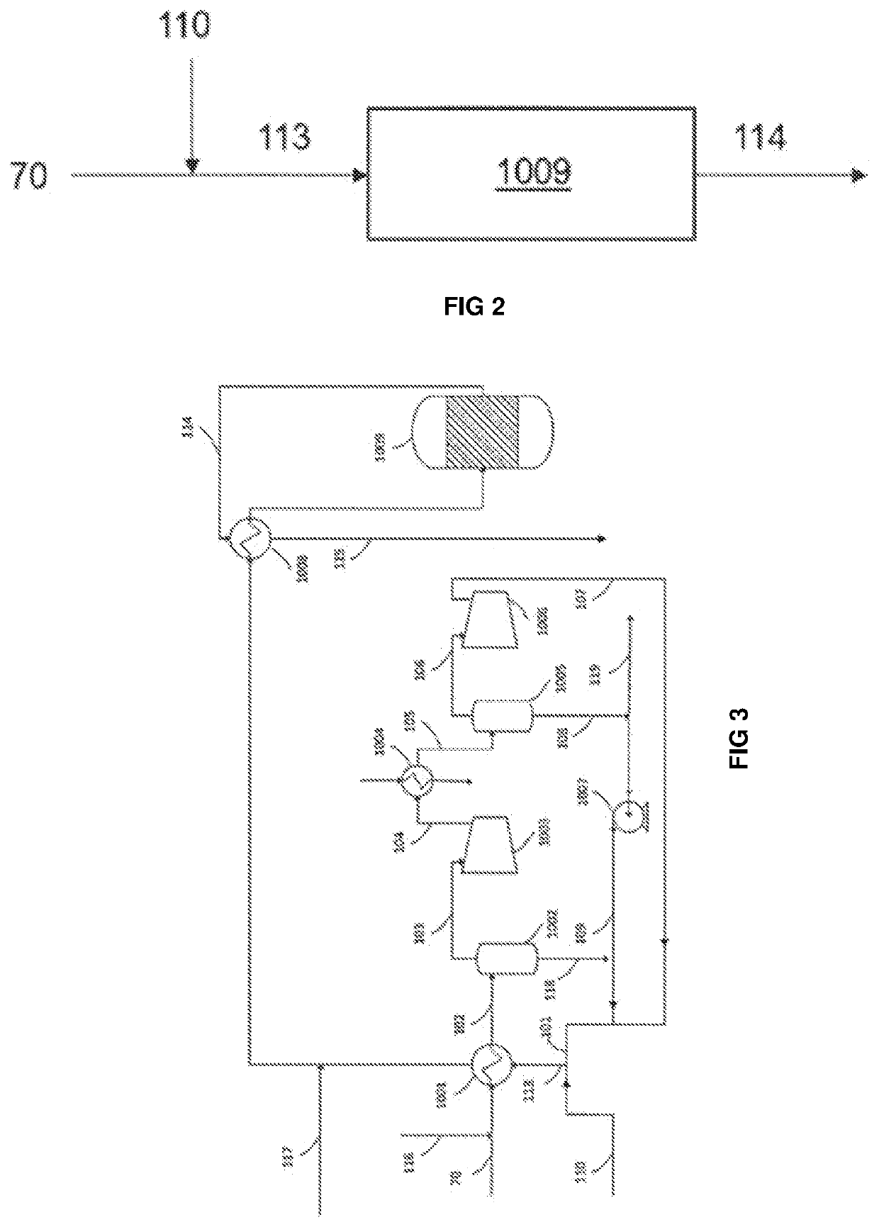
A process for producing a syngas containing CO and H2 from a stream of light hydrocarbons and from combustion flue gases from a cement clinker production unit comprising at least one calcining kiln (300), and a means for discharging the combustion flue gases (500) from the calcining kiln to the outside of said unit, said process comprising the following steps:at least some of the combustion flue gases (70) obtained in said clinker production unit are collected upstream of said means for discharging the combustion flue gases (500);a reaction stream (113) comprising a stream of light hydrocarbons (110) containing methane and the combustion flue gases (70) is prepared;said reaction stream (113) is sent to a tri-reforming reactor (1009) to obtain a syngas (114).

Description

TECHNICAL FIELD[0001]The invention relates to the field of the production of syngas using a tri-reforming reaction by means of combustion flue gases from a cement clinker production unit. The syngas obtained makes it possible to produce paraffinic or olefinic hydrocarbons, which are high-quality liquid fuel bases (diesel fraction with a high cetane index, kerosene, etc.) or petrochemical bases, that can be obtained more particularly by means of a Fischer-Tropsch synthesis step.PRIOR ART[0002]Several processes for producing syngas from carbon-based materials, in particular the partial oxidation reaction and methane reforming, are known.[0003]Partial oxidation, or gasification by partial oxidation (known by the initials PDX), consists in forming, by combustion under sub-stoichiometric conditions, a mixture at high temperature, generally between 1000° C. and 1600° C., of, on the one hand, carbon-based material and, on the other hand, of air or oxygen, in order to oxidize the carbon-bas...

Claims


Application Information

Patent Timeline
Patent Type & Authority Applications(United States)
IPC IPC(8): C01B3/38C04B7/36
CPCC01B2203/0244C01B2203/1047C04B7/367C04B2290/20C01B2203/143C01B3/382C01B2203/062C01B2203/0811C01B2203/0238Y02P40/18Y02P40/121
Inventor FECANT, ANTOINEFAVRE, ALAINGIMENEZ, MICHELSANTOS RAMOS, CARLOS
Owner INST FR DU PETROLE
Learn More