
Sinusoidal modulation method and three phase inverter

a three-phase inverter and sine wave technology, applied in the direction of power conversion systems, efficient power electronics conversion, climate sustainability, etc., can solve the problems of affecting conversion efficiency, affecting the use efficiency, burning or damage of power transistors, etc., to reduce the switching loss of power transistors, improve use efficiency, and prevent the upper and lower arms from being burnt.

Inactive Publication Date: 2019-10-31
NAT CHIAO TUNG UNIV
View PDF7 Cites 18 Cited by
  • Summary
  • Abstract
  • Description
  • Claims
  • Application Information

AI Technical Summary

Benefits of technology

The present invention provides a method and inverter for controlling the modulation of power transistors in a three-phase system. This method solves the problem of short-circuit damage to circuit elements caused by high current when the upper and lower arms are turned on. The method uses a sinusoidal control signal to turn on or turn off the transistors in a specific pattern, reducing switching losses and improving efficiency. The method also allows for control of each phase arm independently, eliminating the need for a dead time to prevent short-circuit damage and ensuring accurate pulse signals. Additionally, the method does not require any additional hardware or protection circuits, reducing costs.

Problems solved by technology

However, when the upper and lower bridge power transistors are switched quickly based on the pulse width modulation (PWM) signal, their dv / dt dynamic effect often increases the instability of the transistor gate drive circuit to cause erroneous conduction, and it results in an instantaneous short circuit of the drive circuit which may burn or damage the power transistors.
In addition, the SPWM or SVPWM modulation method generally uses the dead time of about 1 μs; however, as the switching frequency of the PWM carrier increases, the dead time may cause distortion of the waveform and affect the conversion efficiency.

Method used


Image

  • Sinusoidal modulation method and three phase inverter
  • Sinusoidal modulation method and three phase inverter
  • Sinusoidal modulation method and three phase inverter

Examples


Embodiment Construction

[0030]The following embodiments of the present invention are herein described in detail with reference to the accompanying drawings. These drawings show specific examples of the embodiments of the present invention. It is to be understood that these embodiments are exemplary implementations and are not to be construed as limiting the scope of the present invention in any way. Further modifications to the disclosed embodiments, as well as other embodiments, are also included within the scope of the appended claims. These embodiments are provided so that this disclosure is thorough and complete, and fully conveys the inventive concept to those skilled in the art. Regarding the drawings, the relative proportions and ratios of elements in the drawings may be exaggerated or diminished in size for the sake of clarity and convenience. Such arbitrary proportions are only illustrative and not limiting in any way. The same reference numbers are used in the drawings and description to refer to...


PUM


Abstract

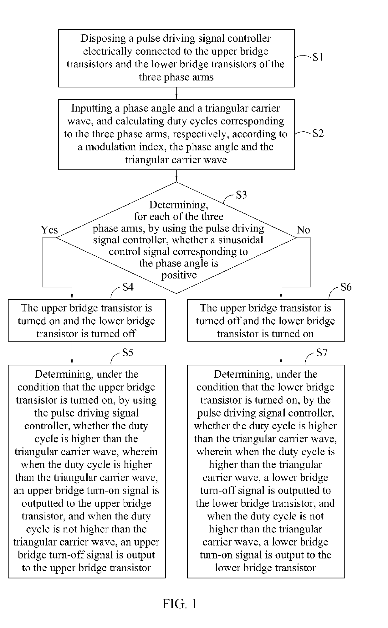
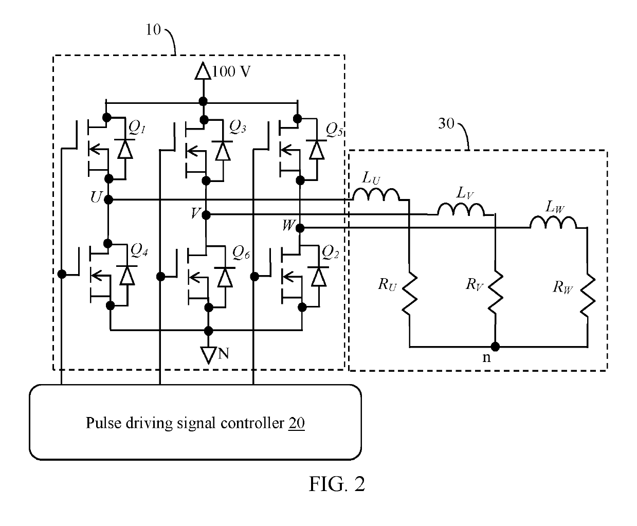
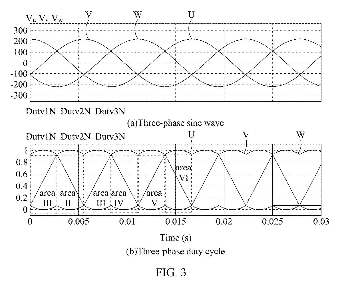
A sinusoidal modulation method and a three-phase inverter are disclosed. A pulse driving signal controller is disposed to connect the three-phase inverter. The pulse driving signal controller controls the transistors of the three-arm full-bridge architecture. By examining the phase angle of the output current, operations of the upper and lower bridge power transistors can be adjusted, so that three power transistors are turned on and the other three power transistors are turned off during the PWM operations. As a result, the dead time is not required to set during the PWM operation for preventing a short-circuit due to dynamic switching errors of the upper and lower bridge power transistors. The requirements of the hardware circuits can be also reduced.

Description

CROSS-REFERENCE TO RELATED APPLICATION[0001]This application claims the benefit of Taiwan Patent Application No. 107114321, filed on Apr. 26, 2018, in the Taiwan Intellectual Property Office, the disclosure of which is incorporated herein in its entirety by reference.BACKGROUND OF THE INVENTION1. Field of the Invention[0002]The present invention generally relates to a sinusoidal modulation method and a three-phase inverter using the same, more particularly to a no-dead-time sinusoidal modulation method which is able to adjust operations of upper and lower bridge power transistors according to a sinusoidal current phase angle, and a three-phase inverter using the same.2. Description of the Related Art[0003]The existing three-phase AC sine-wave driver can be used to a motor or a DC / AC inverter. In recent years, the conventional driving methods are sinusoidal pulse width modulation (SPWM) and space vector pulse width modulation (SVPWM). These manners all use complementary switching ope...

Claims


Application Information

Patent Timeline
Patent Type & Authority Applications(United States)
IPC IPC(8): H02M7/5387
CPCH02M7/53871H02M7/5395H02M1/38H02M1/4233Y02B70/10H02M1/0003
Inventor JENG, SHYR-LONGWU, CHIH-CHIANGCHIENG, WEI-HUA
Owner NAT CHIAO TUNG UNIV
Learn More