
Isolation Transformer with Low Unwanted Resonances, Energy Transfer Device Having an Isolation Transformer and Energy Transfer Device for Wireless Transfer of Energy Having an Isolation Transformer

a technology of unwanted resonance and isolation transformer, which is applied in the direction of fixed transformers or mutual inductances, inductances, magnetic cores of transformers/inductances, etc. it can solve the problems of energy efficiency reduction, leakage current reduction, energy loss, etc., and reduce unwanted resonances , increase the coupling factor of an associated energy transfer system

Active Publication Date: 2019-10-31
EPCOS AG
View PDF6 Cites 2 Cited by
  • Summary
  • Abstract
  • Description
  • Claims
  • Application Information

AI Technical Summary

Benefits of technology

The patent describes a special type of transformer that reduces resonances, which can interfere with energy transfer and make it less efficient. By reducing resonances, the transformer increases the coupling factor, which helps to transfer energy more effectively, and reduces interference in the surrounding area. This results in a more efficient and reliable energy transfer device.

Problems solved by technology

One problem in systems for wireless energy transfer, in particular at high electrical powers, is energy loss due to low magnetic coupling between the two abovementioned coils.
Parasitic inductive and capacitive elements within the path which the energy takes lead to leakage currents.
In particular, resonances of matching elements can be formed by parasitic reactance elements of this kind and lead to a reduction in energy efficiency.
In this case, unwanted resonances can occur at the operating frequency of the energy transfer system or at higher-order harmonics.
Electromagnetic contamination of the area surrounding the energy transfer system is likewise disadvantageous since electrical power which is emitted but is not absorbed by the receiving coil is generally coupled in an unwanted manner to the surrounding area.
Moreover, common-mode interference-suppression chokes act only to a limited extent against interfering differential-mode resonances.

Method used


Image

  • Isolation Transformer with Low Unwanted Resonances, Energy Transfer Device Having an Isolation Transformer and Energy Transfer Device for Wireless Transfer of Energy Having an Isolation Transformer
  • Isolation Transformer with Low Unwanted Resonances, Energy Transfer Device Having an Isolation Transformer and Energy Transfer Device for Wireless Transfer of Energy Having an Isolation Transformer
  • Isolation Transformer with Low Unwanted Resonances, Energy Transfer Device Having an Isolation Transformer and Energy Transfer Device for Wireless Transfer of Energy Having an Isolation Transformer

Examples


Embodiment Construction

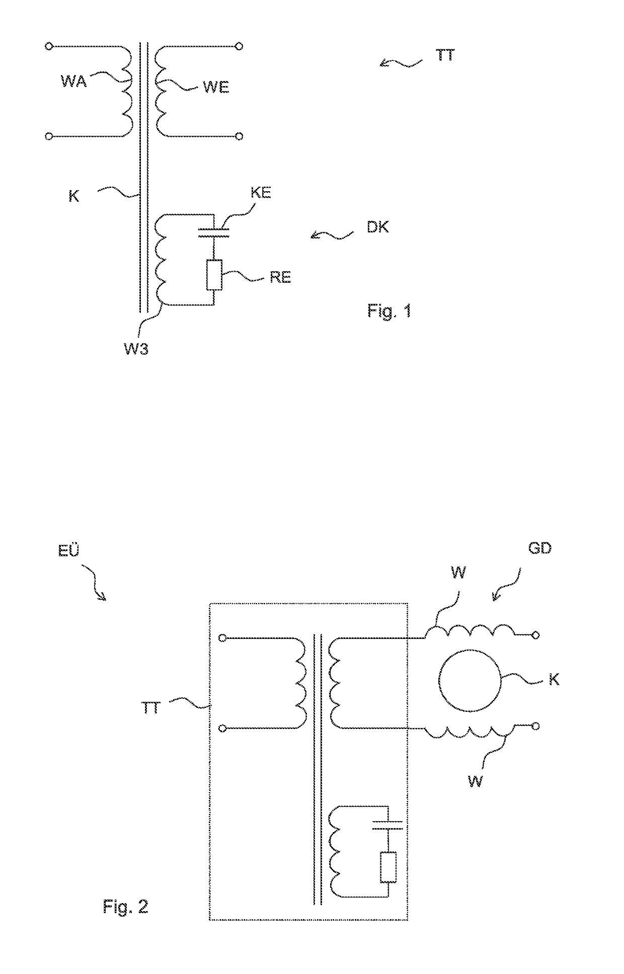
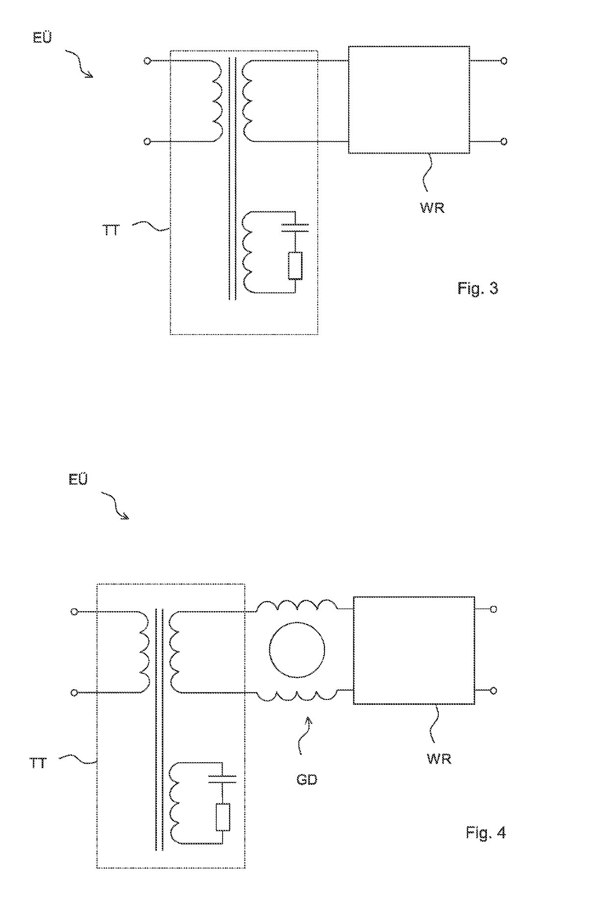
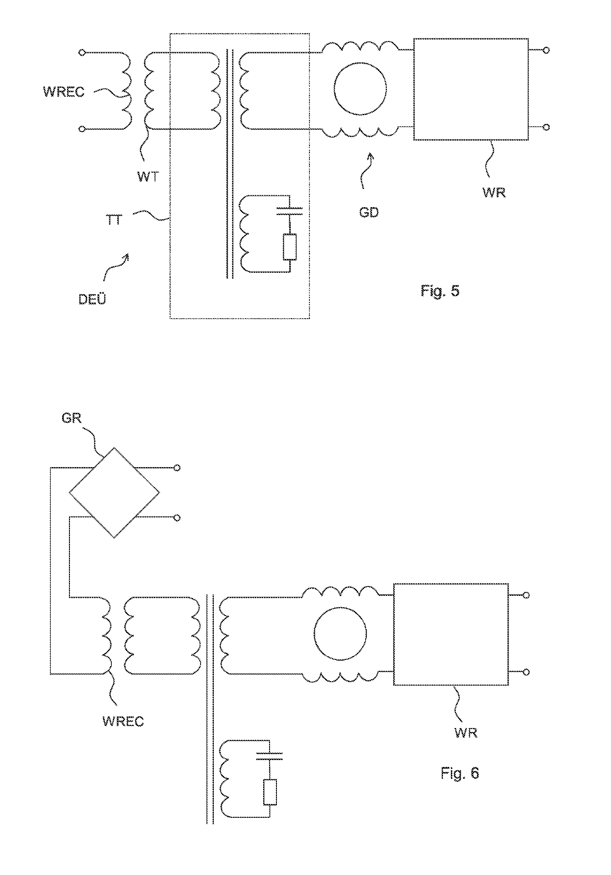
[0042]FIG. 1 shows an equivalent circuit diagram of an improved isolation transformer IT which has an input winding WP and an output winding WA. The input winding WP and the output winding WA are magnetically coupled by means of a transformer core K. In addition, the isolation transformer TT has an attenuation circuit DK which has a third turn W3, a capacitive element KE and a resistive element RE. The third turn W3 is also magnetically coupled to the input winding WP and to the output winding WA by means of the transformer core K. The transformer core K is schematically illustrated. The transformer core K can be of rod-shaped design or form a magnetically closed circuit, for example, a U-shaped core with a yoke.

[0043]The attenuation circuit DK of the transformer core TT attenuates critical frequencies, so that critical resonances, which would lead to unwanted resonance, cannot even be produced in the first place.

[0044]FIG. 2 shows the optional circuit of the isolation transformer T...


PUM

PropertyMeasurementUnit
electrical resistanceaaaaaaaaaa
capacitanceaaaaaaaaaa
inductanceaaaaaaaaaa

Abstract

An isolation transformer and an energy transfer device having an isolation transformer are disclosed. In an embodiments an isolation transformer includes an input winding, an output winding, a third winding, a capacitive element and a resistive element, wherein the capacitive element, the resistive element and the third winding are connected in series, and wherein the input winding, the output winding and the third winding are magnetically coupled.

Description

[0001]This patent application is a national phase filing under section 371 of PCT / EP2016 / 078069, filed Nov. 17, 2016, which claims the priority of German patent application, filed, each of which is incorporated herein by reference in its entirety.TECHNICAL FIELD[0002]The invention relates to isolation transformers in which unwanted resonances are suppressed. The invention further relates to energy transfer devices, for example, for wireless energy transfer, having isolation transformers of this kind.BACKGROUND[0003]In systems for wireless energy transfer by energy transfer devices, electrical energy is, for example, by magnetic coupling, emitted by means of a transmitting coil and received by a receiving coil. In this way, mobile communication devices and motor vehicles can be charged in a contactless manner. Energy transfer devices of this kind can comprise an isolation transformer which provides galvanic isolation between an energy source and the transmitting coil.[0004]One proble...

Claims


Application Information

Patent Timeline
Patent Type & Authority Applications(United States)
IPC IPC(8): H01F27/42H02J50/12H01F38/14H01F27/28H01F27/24
CPCH01F27/28H01F27/42H01F38/14H01F27/24H02J50/12H02J7/025H01F27/38H01F2019/085
Inventor BECK, FABIAN
Owner EPCOS AG
Learn More