Intake air cooling apparatus abnormality detection system for internal combustion engine
a cooling apparatus and abnormal detection technology, applied in the direction of machines/engines, combustion-air/fuel-air treatment, electric control, etc., can solve the problems of thermal damage to a component, abnormality may not be detected, etc., to reliably detect abnormalities and accurately determine the load state of the internal combustion engine
- Summary
- Abstract
- Description
- Claims
- Application Information
AI Technical Summary
Benefits of technology
Problems solved by technology
Method used
Image
Examples
first embodiment
[0028]A first embodiment of the present disclosure will herein be described in detail with reference to the drawings.
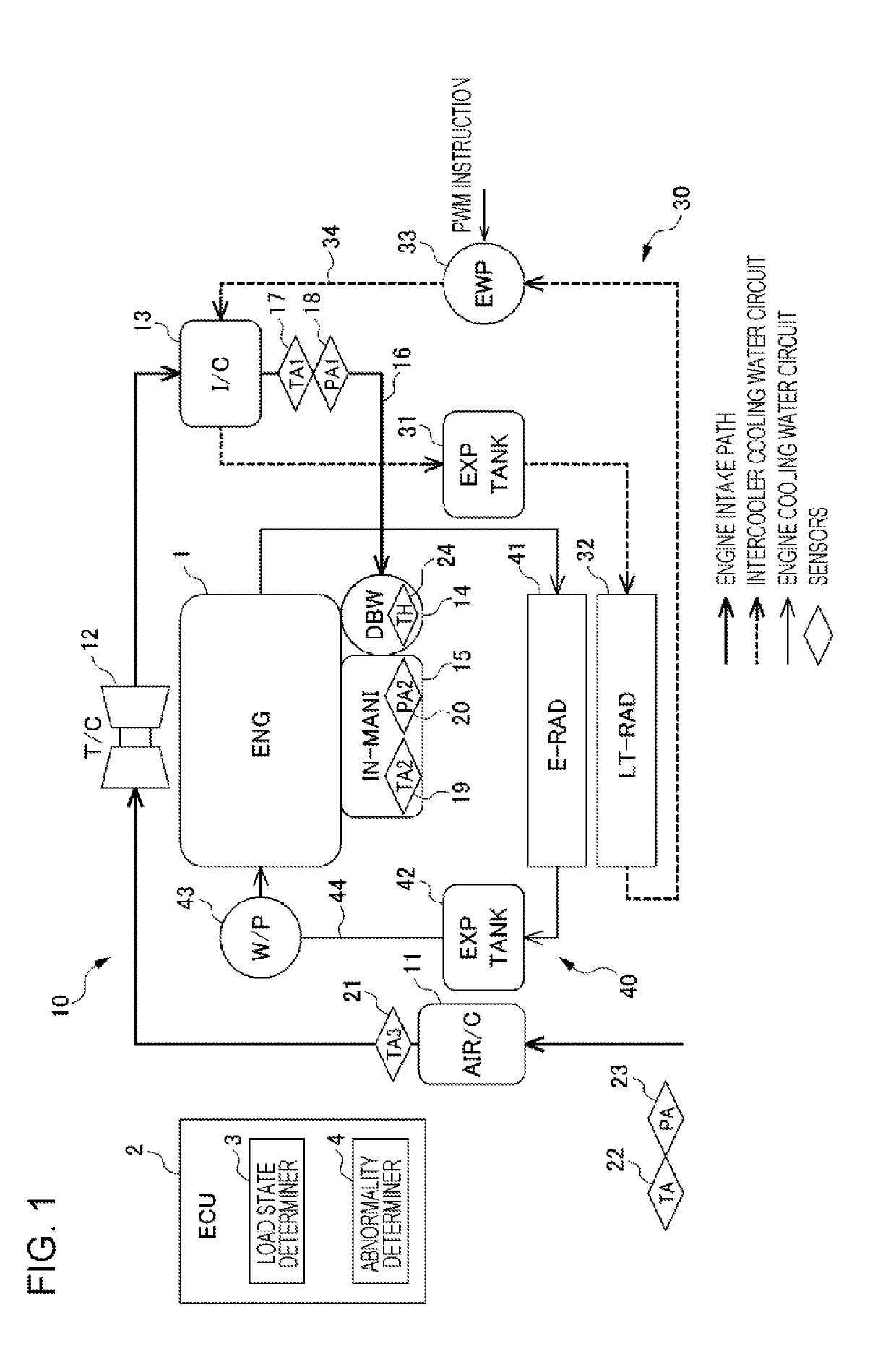
[0029]FIG. 1 illustrates an exemplary configuration of an engine 1 serving as an internal combustion engine, an engine intake path 10, an intercooler cooling water circuit 30 serving as an intake air cooling apparatus, an engine cooling water circuit 40, and an electronic control unit (ECU) 2 controlling the above components, according to the first embodiment.
[0030]The engine 1 is a gasoline engine that directly injects fuel into a combustion chamber of each cylinder (not illustrated). A fuel injection valve (not illustrated) is provided for each cylinder. The opening times and the closing times of the fuel injection valves are controlled by the ECU 2. The ECU 2 also controls, for example, a turbo charger 12 and a throttle valve 14 on the engine intake path described below.
[0031]The engine intake path 10 is coupled at the upstream side of the engine 1. On the engine i...
second embodiment
[0098]An intake air cooling apparatus abnormality detection system according to a second embodiment of the present disclosure will herein be described in detail with reference to the drawings. The same reference numerals are used in the second embodiment to identify the same components in the first embodiment. A description of such components is omitted herein.
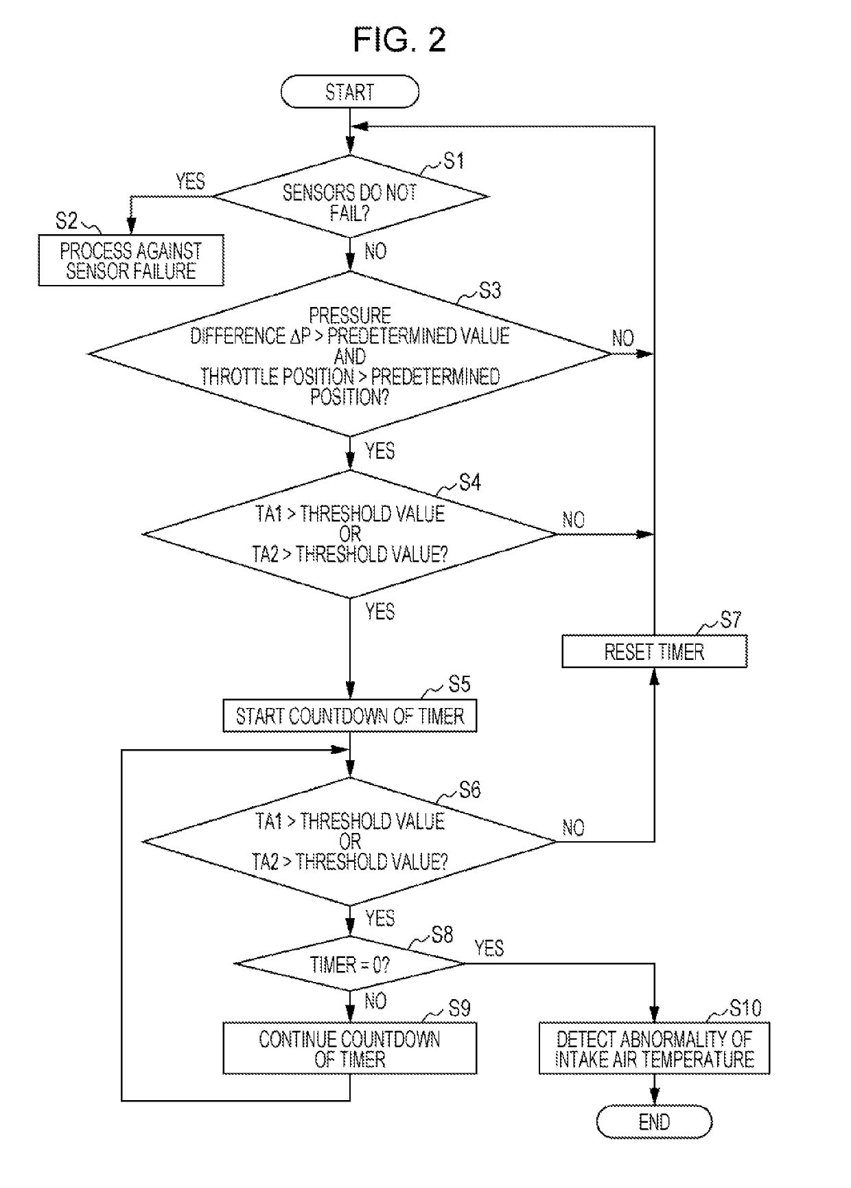
[0099]FIG. 5 is a flowchart in the second embodiment.
[0100]In the second embodiment, as illustrated in FIG. 5, Step 11 for setting the timer is inserted between Step S4 and Step S5 in the flowchart in the first embodiment illustrated in FIG. 2.
[0101]In general, the intake air temperature is rapidly increased as the degree of supercharge by the turbo charger 12 is increased. Accordingly, it is preferred that an abnormality in the intercooler cooling water circuit 30 be rapidly detected as the degree of supercharge by the turbo charger 12 is higher.
[0102]The pressure difference ΔP between the atmospheric pressure PA and the pres...
PUM
 Abstract
Description
Claims
Application Information
 - R&D Engineer
- R&D Manager
- IP Professional
- Industry Leading Data Capabilities
- Powerful AI technology
- Patent DNA Extraction
Browse by: Latest US Patents, China's latest patents, Technical Efficacy Thesaurus, Application Domain, Technology Topic, Popular Technical Reports.
© 2024 PatSnap. All rights reserved.Legal|Privacy policy|Modern Slavery Act Transparency Statement|Sitemap|About US| Contact US: help@patsnap.com


