Aircraft With Load Reducing Wing Like Element

a technology of reducing wing and wing root, applied in the field of aircraft, can solve the problems of reducing the effective lever arm relative to the wing root, adding bending moments in the wing region, etc., and achieve the effect of reducing the load acting on the aircraft structur

Inactive Publication Date: 2019-10-31
DEUTSCHES ZENTRUM FUER LUFT & RAUMFAHRT EV +1
View PDF2 Cites 2 Cited by
  • Summary
  • Abstract
  • Description
  • Claims
  • Application Information

AI Technical Summary

Benefits of technology

[0013]The torque control device constitutes an apparatus, which is arranged in a structurally fixed position on the aircraft and which enables an additional wing-like element to rotate by means of the rotatable interface means when attached thereto. The allowed degree of rotation depends on the torque that acts on the interface means, which torque results from the aerodynamic force acting on the additional wing-like element depending on its size and shape as well as on the location and orientation of the rotational axis. Further, the degree of rotation depends on the characteristics or behaviour of the torque control means, which influences the rotation of the interface means as a reaction on the torque introduced by the wing-like element. The torque control means may be realized as a passive device, which is based on a spring arrangement. This leads to a simplified design of the torque control means and the arrangement of a winglet device on the aircraft.
[0037]Further, the aircraft according to the invention may comprise a wing-like element at a forward portion of the fuselage forward of the wing. A control of the angle of incidence of such a canard is beneficial as it reduces the effects of gusts onto the aircraft if fitted with a canard. It goes without saying, that the wing-like element in this embodiment may comprise a rotational axis, which may be arranged parallel to the lateral (y) axis of the aircraft, in a slightly upward direction or a slightly downward direction, i.e. in a range of about 15°-20° in either direction of the horizontal (y) axis of the aircraft.

Problems solved by technology

A widespread use of large wing tip devices on aircraft has the effect of increased structural loads, which lead to additional bending moments in the wing region, particularly in the wing root region.
However, due to the fact that wing tip devices are often greatly curved upwards, which leads to the control surfaces acting at a rather large angle to a horizontal plane, an effective lever arm relative to the wing root is reduced compared with control surfaces arranged at further inboard locations on a wing.
Further, modern wing tip devices are often provided with great transitional arcs and have only small planar areas or none at all.

Method used


Image

  • Aircraft With Load Reducing Wing Like Element
  • Aircraft With Load Reducing Wing Like Element
  • Aircraft With Load Reducing Wing Like Element

Examples


Embodiment Construction

[0045]FIG. 1a shows a wing 2 attached to a fuselage (not shown) of an aircraft, the wing 2 having a wing end 4, to which a wing tip device 6 is mounted. Exemplarily, the wing tip device 6 comprises a planar winglet 8 as well as a curved transition region 10 extending between a connection region 12 of the planar winglet 8 and the wing end 4 of the wing 2. The planar winglet 8 extends at an almost upright angle to an x-y-plane of the aircraft. The wing tip device 6 produces an additional structural load on the aircraft structure due to aerodynamic and mass forces, depending on the actual flight state. Exemplarily, the wing tip device 6 is shown in a flight state.

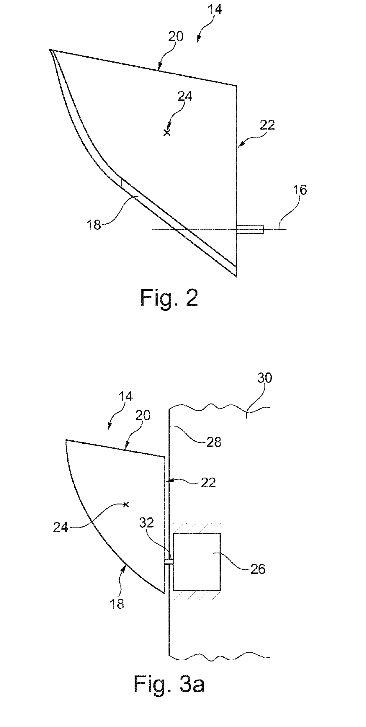
[0046]Exemplarily, a wing-like element 14 is placed on a lower side of the transition region and extends in a span-wise direction, thereby leading to an increase in wing span. As indicated by a dash-dotted line, the wing-like device 14 is rotatable about a rotational axis 16, which is explained in further detail below. The win...


PUM


Abstract

An aircraft includes a fuselage, a wing attached thereto, a wing tip device attached to a wing end of the wing (2), a wing-like element having a wing root, a wing leading edge and a wing trailing edge, and a torque control device having a rotatable interface means. The torque control device is adapted for rotatably supporting the wing root of the wing-like element on the interface means about a rotational axis extending from the interface means into the wing-like element and to limit the degree of rotation depending on a torque introduced into the interface means by the wing-like element. The wing-like element is adapted to induce a rotation around the rotational axis in an air flow. The wing root is coupled with the wing tip device, the wing or the fuselage through the torque control device such that the leading edge extends into an airflow surrounding the aircraft.

Description

TECHNICAL FIELD[0001]The invention relates to an aircraft with a fuselage, a wing attached to the fuselage, a wing tip device attached to a wing and of the wing and at least one wing like element.BACKGROUND OF THE INVENTION[0002]A widespread use of large wing tip devices on aircraft has the effect of increased structural loads, which lead to additional bending moments in the wing region, particularly in the wing root region. The reduction or prevention of increased maximum loads on the aircraft, especially under the influence of gusts or severe manoeuvring, may be achieved through load alleviation systems. These may include adjustable control surfaces, located at wing trailing edges or further forward wing sections. Integration of these control surfaces into wing-tip-devices is another possible approach.[0003]However, due to the fact that wing tip devices are often greatly curved upwards, which leads to the control surfaces acting at a rather large angle to a horizontal plane, an ef...

Claims


Application Information

Patent Timeline
Patent Type & Authority Applications(United States)
IPC IPC(8): B64C3/38B64C13/02
CPCB64C3/385B64C13/02B64C3/56B64C5/08B64C23/065Y02T50/10
Inventor THEURICH, FRANKHIMISCH, JAN
Owner DEUTSCHES ZENTRUM FUER LUFT & RAUMFAHRT EV
Why Eureka
Try Eureka