
Patch-type sensor module

a sensor module and patch-type technology, applied in the direction of optical radiation measurement, electrical apparatus casing/cabinet/drawer, instruments, etc., can solve the problems of inconvenient monitoring of body temperature in real time or periodically, inconvenient use of separate sensors or equipment, and cumbersome measurement of body temperature, etc., to achieve continuous use and easy charging

Active Publication Date: 2019-10-31
AMOLIFESCI CO LTD
View PDF0 Cites 10 Cited by
  • Summary
  • Abstract
  • Description
  • Claims
  • Application Information

AI Technical Summary

Benefits of technology

The patch-type sensor module described in this patent allows for real-time monitoring of biometric data through a sensor. This data can be transmitted outside of the device using a communication module, such as a Bluetooth or Wi-Fi device. This allows for quicker response times in case of emergency situations. Additionally, the module includes a battery that can be easily charged and used continuously without replacement. No physical driving button is needed, allowing for a thinner and more streamlined design. Overall, the patch-type sensor module provides improved monitoring and tracking of biometric data.

Problems solved by technology

Accordingly, since people around babies, infants, and patients with mobility difficulties should help them to maintain a state of wearing a thermometer on their bodies, there is a problem of measuring a body temperature being cumbersome.
Further, since the conventional thermometer is in contact with a body of a target person for a certain period of time and then is separated from the body of the target person so that a body temperature is checked, checking the body temperature in real time or periodically is inconvenient.
In addition, since the conventional thermometer is able to measure only the body temperature, there is a problem in that a separate sensor or equipment is inevitably required so as to acquire other information from the target person.

Method used


Image

  • Patch-type sensor module
  • Patch-type sensor module
  • Patch-type sensor module

Examples


Embodiment Construction

[0039]Hereinafter, embodiments of the present invention will be fully described in detail which is suitable for easy implementation by those skilled in the art to which the present invention pertains with reference to the accompanying drawings. The present invention may be implemented in various different forms, and thus it is not limited to the embodiments which will be described herein. In the drawings, some portions not related to the description will be omitted in order to clearly describe the present invention, and the same or similar reference numerals are assigned to the same or similar components throughout this disclosure.

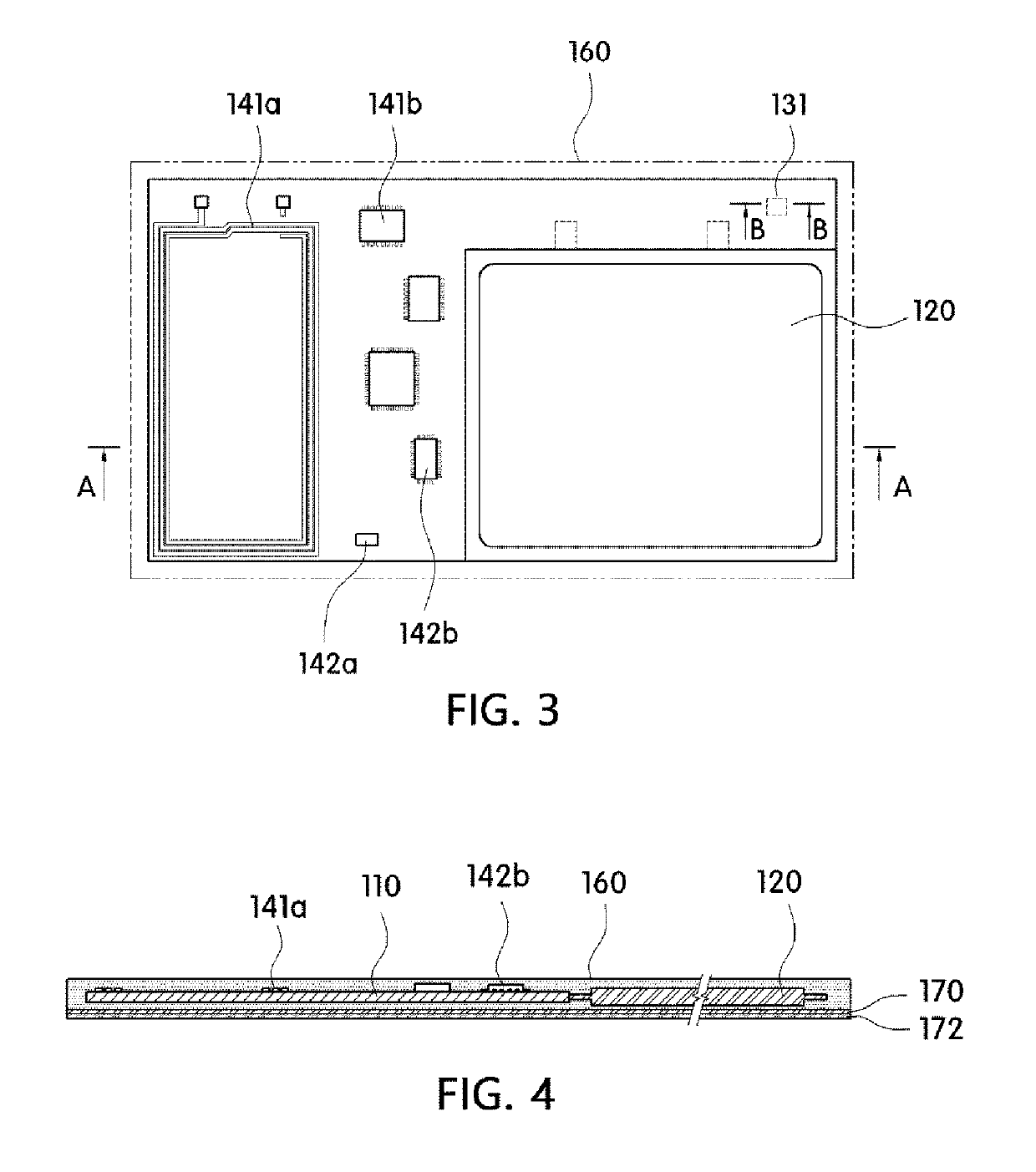
[0040]As shown in FIGS. 1 to 16, a patch-type sensor module 100, 200, 300, or 400 according to one embodiment of the present invention includes a flexible circuit board 110, a power supply unit 120, a sensing unit 130 or 230, a communication unit 140, a control unit 150, and a protection member 160.

[0041]The flexible circuit board 110 is a substrate on whi...


PUM

PropertyMeasurementUnit
pore diameteraaaaaaaaaa
poweraaaaaaaaaa
flexibleaaaaaaaaaa

Abstract

A patch-type sensor module is provided. A patch-type sensor module according to one embodiment of the present invention comprises: a power supply unit electrically connected with a flexible circuit board; a sensing unit which is mounted on the flexible circuit board and includes a temperature sensor for measuring a user's body temperature; a communication unit which allows power to be supplied using a wake-up function, wherein a pairing with an external communication module is concurrently established when power is supplied, and information measured through the sensing unit is then transmitted to the external communication module; a control unit for controlling operations of the power supply unit, the sensing unit, and the communication unit; and a protection member for preventing the flexible circuit board, the power supply unit, the sensing unit, the communication unit, and the control unit from being exposed to the outside.

Description

TECHNICAL FIELD[0001]The present invention relates to a patch-type sensor module, and more particularly, to a patch-type sensor module which is capable of acquiring biometric data of a user.BACKGROUND ART[0002]Generally, in measuring of a body temperature and a heartbeat of a body, thermometers of a contact type and a non-contact type may be used. Examples of general thermometers include a mercury thermometer, an alcohol thermometer, an infrared sensor thermometer, and the like.[0003]These thermometers may acquire information on the body temperature after waiting for a certain period of time in a state of being worn on or being in contact with the body.[0004]Accordingly, since people around babies, infants, and patients with mobility difficulties should help them to maintain a state of wearing a thermometer on their bodies, there is a problem of measuring a body temperature being cumbersome.[0005]Further, since the conventional thermometer is in contact with a body of a target perso...

Claims


Application Information

Patent Timeline
Patent Type & Authority Applications(United States)
IPC IPC(8): A61B5/00H05K1/18H05K5/06H05K5/02G01J1/42G01K13/00A61B5/01A61B5/0205H04W4/80H04B5/00H04W12/06H04W12/00
CPCG01J1/429A61B2562/029H04W12/00407A61B2562/164A61B5/01H05K5/0247A61B5/0006H04B5/0037A61B2560/0412A61B5/04087A61B5/02055H05K1/189H05K5/065G01K13/002A61B5/0008H05K2201/10037A61B2562/18A61B5/6833H05K2201/10098A61B2560/0214H04W4/80H05K2201/10151H04W12/06A61B5/04085A61B5/002G01D21/02A61B2503/04A61B2505/07A61B2562/0271A61B2562/0209G01J1/0219G01J1/0228H04W4/38G01K13/20A61B5/332H04W12/47H04B5/79A61B5/282A61B5/28
Inventor KIM, BEOM JINCHUNG, YUN HEELEE, JI HYUNRYU, KYUNG HYUN
Owner AMOLIFESCI CO LTD
Learn More