
Engine Nacelle Heat Exchanger

a technology of heat exchanger and engine, which is applied in the direction of efficient propulsion technology, machines/engines, transportation and packaging, etc., can solve the problems that the increase in heat load may require additional heat dissipation, and achieve the effect of reducing drag from a baseline and reducing inlet spillag

Active Publication Date: 2019-10-24
LOCKHEED MARTIN CORP
View PDF10 Cites 6 Cited by
  • Summary
  • Abstract
  • Description
  • Claims
  • Application Information

AI Technical Summary

Benefits of technology

The patent text describes a system for exchanging heat between a fluid flowing within a heat exchanger and air ventilating the nacelle using a seal around an opening of the nacelle. The system may provide advantages such as reducing drag, controlling heat exchange, and addressing flames or fire within the nacelle. The technical effects may be improved efficiency and safety.

Problems solved by technology

This increased heat load may require additional heat dissipation to maintain the aircraft within operating range.

Method used


Image

  • Engine Nacelle Heat Exchanger
  • Engine Nacelle Heat Exchanger
  • Engine Nacelle Heat Exchanger

Examples


Embodiment Construction

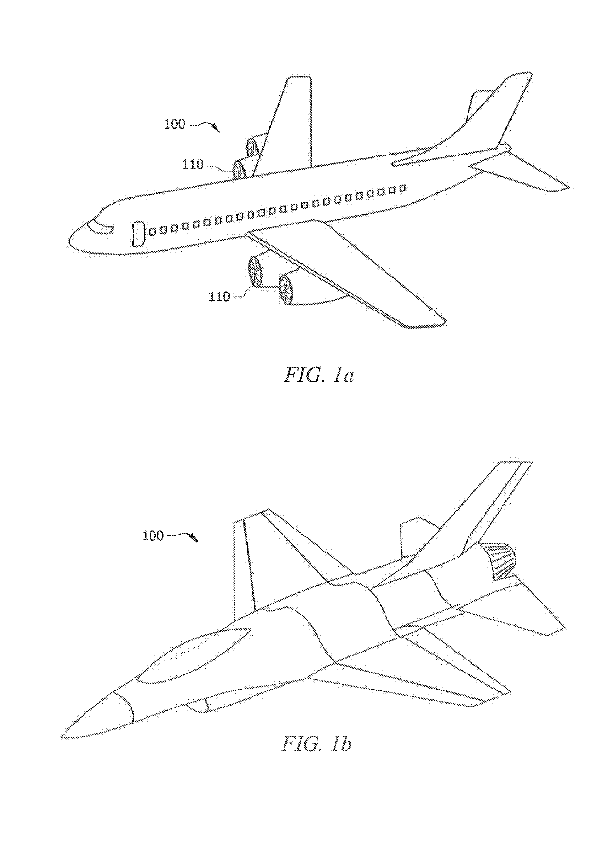
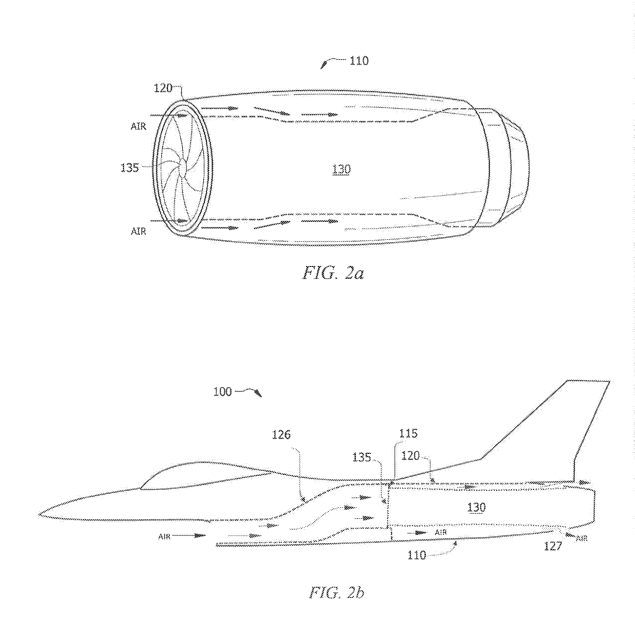
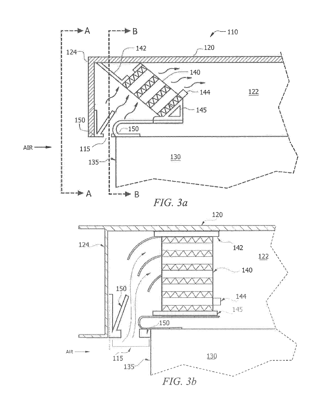
[0032]To facilitate a better understanding of the present disclosure, the following examples of certain embodiments are given. The following examples are not to be read to limit or define the scope of the disclosure. Embodiments of the present disclosure and its advantages are best understood by referring to FIGS. 1 through 6, where like numbers are used to indicate like and corresponding parts.

[0033]Heat dissipation for aircraft presents a growing problem, as more systems in the aircraft are generating larger amounts of heat. For example, more sophisticated electrical, communications, or control systems require additional heat dissipation, and in some cases, require active cooling. Conventional techniques to enhance heat dissipation within an aircraft have required the use of external scoops or structures to capture ram air. The external scoops may direct the air into the aircraft and through a heat exchanger. The use of these external structures to capture the ram air induces sign...


PUM


Abstract

A nacelle for an engine includes an exterior housing a least partially surrounding the engine. The nacelle further includes a front portion proximate an engine face of the engine. The front portion of the nacelle defines an opening into an interior of the nacelle. The nacelle further includes a seal disposed proximate the opening. The seal is configured to selectively allow air into the interior of the nacelle. The nacelle further includes a heat exchanger disposed within the interior of the nacelle. The heat exchanger is configured to exchange heat between a fluid flowing within the heat exchanger and air at the interior of the nacelle.

Description

TECHNICAL FIELD[0001]This disclosure relates in general to engine nacelles, and more particularly to engine nacelles with one or more heat exchangers.BACKGROUND[0002]Aircraft may generate heat through operation of on-board systems, such as its engines, communications systems, or electronics control systems. As aircraft are modernized, the amount of heat generated by the aircraft may increase. This increased heat load may require additional heat dissipation to maintain the aircraft within operating range.SUMMARY OF THE DISCLOSURE[0003]According to one embodiment, a nacelle for an engine includes an exterior housing at least partially surrounding the engine. The nacelle further includes a front portion proximate an engine face of the engine. The front portion of the nacelle defines an opening into an interior of the nacelle. The nacelle further includes a seal disposed proximate the opening. The seal is configured to selectively allow air into the interior of the nacelle. The nacelle ...

Claims


Application Information

Patent Timeline
Patent Type & Authority Applications(United States)
IPC IPC(8): F02C7/18B64D33/02B64D33/08F01D25/24F02C7/28F02C7/25
CPCB64D33/08F05D2240/55F05B2260/20B64D33/02F02C7/25F01D25/24F02C7/18F05B2240/14F02C7/28B64D2033/024B64D33/10B64D2033/0286B64D2045/009F02C7/14F05D2240/14F05D2260/213Y02T50/60
Inventor MCGEE, MARK G.BOROVSKY, ROBERTBRUNSON, TROY DONJACKSON, LORI KAYSTACEY, DEVIN A.COX, CAREY F.
Owner LOCKHEED MARTIN CORP
Learn More