Floating Tile

a technology of floating tiles and covers, applied in the field of new floating tiles, can solve the problems of limited durability and life, inadequacies of long-term resistance, and difficulty in deployment and retrieval, and achieve the effect of unrestricted freedom of movemen

Inactive Publication Date: 2019-10-24
EFTEKHARZADEH SHAHRIAR
View PDF0 Cites 0 Cited by
  • Summary
  • Abstract
  • Description
  • Claims
  • Application Information

AI Technical Summary

Benefits of technology

The present invention provides a cost-effective, durable, and practical solution for covering large open water surfaces. The invention consists of a floating tile made up of a thin layer of protective concrete at the surface, a layer of buoyant material underneath, and a two-compartment container made of plastic that provides housing for the protective and buoyant layers plus adequate submergence depth for stability. The lower compartment of the tile is designed to allow for large relative vertical movement between adjacent tiles without piling on top of each other. The invention is not susceptible to sagging or surface puddles and is fully effective in accomplishing its intended purposes.

Problems solved by technology

There are a number of issues with flexible floating membranes that include formation of surface puddles due to sagging and hence the need for drainage, inadequate long-term resistance to ultraviolet (UV) radiation and limited durability and life, chemical instability and leakage of pollutants from the membranes into the water body, difficulty of deployment and retrieval with high tensile strength requirement of the membrane to resist external loads, and cost.
These issues have limited the utility of existing covers to small reservoirs leaving the covering of large open water surface areas impractical.

Method used


Image

  • Floating Tile
  • Floating Tile
  • Floating Tile

Examples


Embodiment Construction

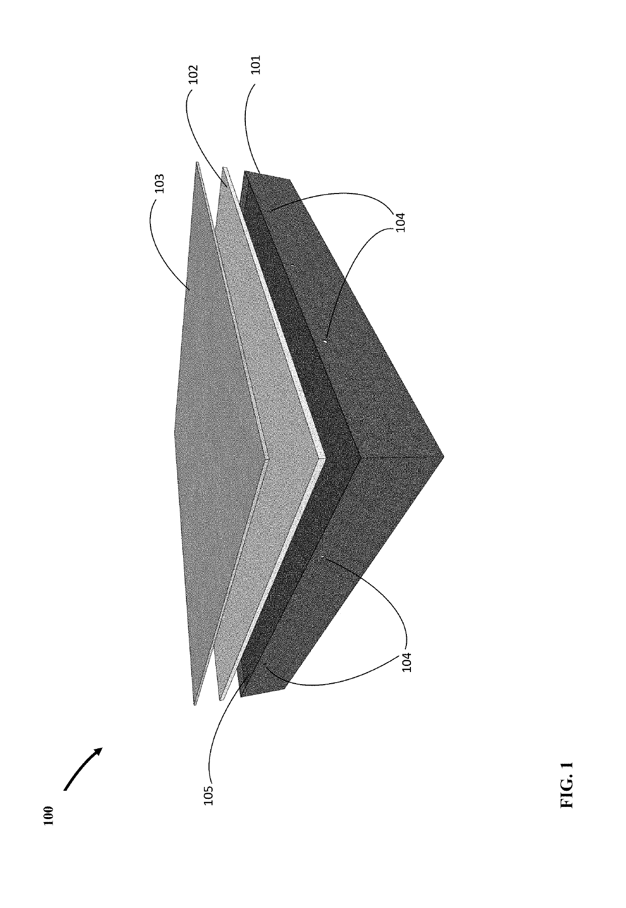
[0020]Referring to FIG. 1 there is shown an expanded view of the preferred embodiment of tile 100 looking from above showing the upper compartment of a two-compartment container 101 with air vent holes 104, a buoyant layer 102, and a layer of protective material such as concrete 103. Protective layer 103 serves as the main element of tile 100 for shielding against ultraviolet radiation (UV). Partition 105 is a flat layer of certain thickness that serves as floor of the upper compartment and ceiling of the lower compartment. The upper compartment is disposed to house buoyant layer 102 and protective layer 103. Container 101 is may be manufactured from thermoplastics such as polyethylene with additives such as carbon black for UV resistance. However, other materials could be used.

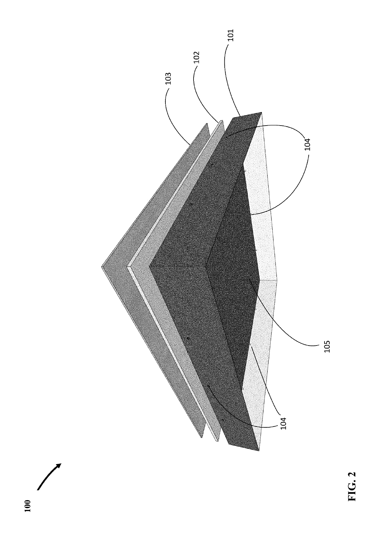
[0021]FIG. 2 shows an expanded view of the preferred embodiment tile 100 looking from below showing the lower compartment of a two-compartment container 101 with air vent holes 104, buoyant layer 102, protect...


PUM

PropertyMeasurementUnit
Thicknessaaaaaaaaaa
Heightaaaaaaaaaa

Abstract

A floating tile for shielding open water surfaces from evaporation and external elements.

Description

FIELD OF THE INVENTION[0001]The present invention pertains to floating covers for open water surfaces. In particular, the present invention provides a new floating tile for shielding open water surfaces from evaporation and external elements.BACKGROUND OF THE INVENTION[0002]The need to cover over large open water surfaces arises from the necessity to prevent water loss through evaporation and to protect the water body from external elements causing pollution. Current solutions are various forms of floating covers comprised of flexible membranes with various means of providing buoyancy for floatation and restraints for the membrane. There are a number of issues with flexible floating membranes that include formation of surface puddles due to sagging and hence the need for drainage, inadequate long-term resistance to ultraviolet (UV) radiation and limited durability and life, chemical instability and leakage of pollutants from the membranes into the water body, difficulty of deploymen...

Claims


Application Information

Patent Timeline
IPC IPC(8): B32B27/06B32B27/32B32B5/18
CPCB32B2255/20B32B2255/102B32B27/065B32B5/18B32B2307/718B32B2307/71B32B27/32B32B2266/0228B32B3/12B32B3/266B32B13/045B32B2250/03B32B2571/00
Inventor EFTEKHARZADEH, SHAHRIAR
Owner EFTEKHARZADEH SHAHRIAR
Why Eureka
Try Eureka