
Rogowski coil with low permeability core

Active Publication Date: 2019-10-10
EATON INTELLIGENT POWER LIMITED
View PDF3 Cites 2 Cited by
  • Summary
  • Abstract
  • Description
  • Claims
  • Application Information

AI Technical Summary

Benefits of technology

The invention is a type of coil called a Rogowski coil, which has a magnetic core and a winding made of conductive wire. The coil has a low relative permeability, which means that it is less affected by magnetic saturation, which can cause the permeability to decrease. The disclosed coil has a relative permeability greater than one but less than twenty. This means that the coil is not very sensitive to changes in magnetic field. The technical effect of this is that the coil produces accurate and consistent results even when the magnetic field is not very strong, which is useful in a variety of applications.

Problems solved by technology

For example, such a low output (typically several hundred microvolts per amp) can create problems for EMI as well as in metering applications.
Further, when the output of the Rogowski coil is a low voltage, the output assembly must include an amplifier which increases the cost and complexity of the output assembly.

Method used


Image

  • Rogowski coil with low permeability core

Examples


Embodiment Construction

[0009]It will be appreciated that the specific elements illustrated in the figures herein and described in the following specification are simply exemplary embodiments of the disclosed concept, which are provided as non-limiting examples solely for the purpose of illustration. Therefore, specific dimensions, orientations, assembly, number of components used, embodiment configurations and other physical characteristics related to the embodiments disclosed herein are not to be considered limiting on the scope of the disclosed concept.

[0010]Directional phrases used herein, such as, for example, clockwise, counterclockwise, left, right, top, bottom, upwards, downwards and derivatives thereof, relate to the orientation of the elements shown in the drawings and are not limiting upon the claims unless expressly recited therein.

[0011]As used herein, the singular form of “a,”“an,” and “the” include plural references unless the context clearly dictates otherwise.

[0012]As used herein, “structu...


PUM


Abstract

A Rogowski coil includes a magnetic core and a winding. The magnetic core includes an encircling body. The winding includes a conductive wire. The winding is disposed in a generally helical coil about the core body.

Description

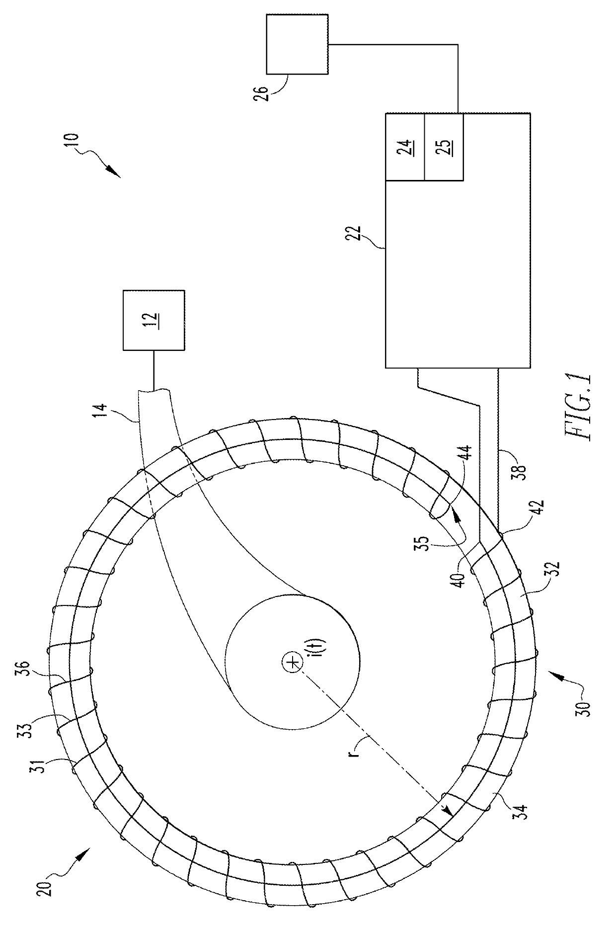
BACKGROUND OF THE INVENTIONField of the Invention[0001]The disclosed and claimed concept relates to a Rogowski coil and, more specifically, to a Rogowski coil including a low permeability core as well as a current sensor assembly including such a Rogowski coil.Background Information[0002]A Rogowski coil is an electrical device generally used to measure alternating current (AC) or high-speed current pulses in another conductor. A Rogowski coil includes a core about which a helical coil of wire is disposed. In one common embodiment, the core is a toxoid. Further, in one common embodiment, the lead from one end of the helical wire returns through the center of the coil to the other end, so that both terminals are at the same end of the coil. This configuration also improves the resistance, or immunity, to external electro-magnetic fields. The whole assembly is then wrapped around another conductor whose current is to be measured. The consistency of the winding density is critical for p...

Claims


Application Information

Patent Timeline
IPC IPC(8): H01F27/24H01F27/28G01R15/18G01R19/00
CPCG01R19/0092H01F27/24G01R15/181H01F27/2823
Inventor MILLER, THEODORE JAMES
Owner EATON INTELLIGENT POWER LIMITED
Learn More