Laminated body, method for producing laminated body, and rearview mirror for vehicle

a laminated body and rearview mirror technology, applied in the direction of instruments, polarising elements, other domestic articles, etc., can solve the problems of frequent exposure of multilayer films to high temperature and humidity, and achieve the effect of favorably suppressing the formation of creases

Active Publication Date: 2019-10-10
FUJIFILM CORP
View PDF0 Cites 0 Cited by
  • Summary
  • Abstract
  • Description
  • Claims
  • Application Information

AI Technical Summary

Benefits of technology

The present invention provides a method for producing a laminated body that can effectively prevent the formation of creases even in high temperature and humidity conditions. This method is also used for producing a rearview mirror for cars that can withstand such harsh conditions.

Problems solved by technology

In such an operating environment, the multilayer film is frequently exposed to high temperature and humidity.

Method used


Image

  • Laminated body, method for producing laminated body, and rearview mirror for vehicle
  • Laminated body, method for producing laminated body, and rearview mirror for vehicle
  • Laminated body, method for producing laminated body, and rearview mirror for vehicle

Examples


example 1

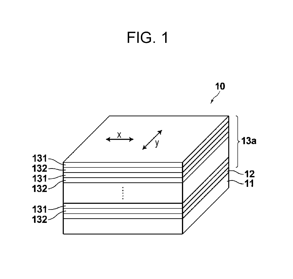
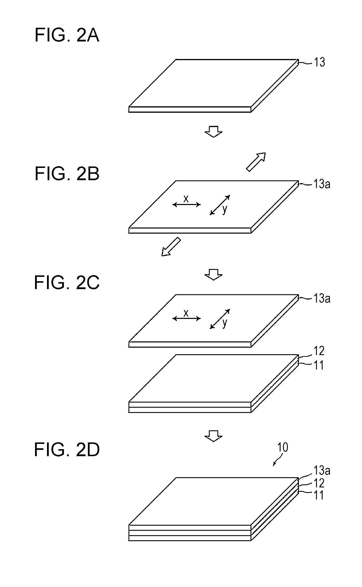
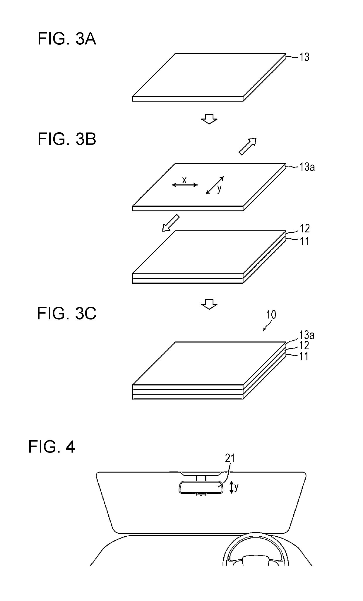
[0059]A reflective-type polarizing plate (manufactured by 3M Japan Limited) was provided as a multilayer film 13 that transmits first polarized light, reflects second polarized light having a polarization axis which intersects the polarization axis of the first polarized light, and has a structure in which birefringent polymers were stacked. Then, the reflective-type polarizing plate was stretched by 1% (stretch factor: 1%) in a polarization axis direction of first polarized light using a high-performance film stretching machine FITZ (manufactured by ICHIKIN Co., Ltd.) in an atmosphere of 25° C. and 60%. When the reflective-type polarizing plate was further stretched, the polarizing plate was broken at a stretch factor of 3%. This showed that the length of the polarizing plate stretched by 1% corresponded to 98% of the breaking length.

Measurement of Glass Transition Point and Thermal Expansion Coefficient

[0060]The reflective-type polarizing plate stretched by 1% in the polarization ...

example 2

[0065]A reflective-type polarizing plate that was not stretched in Example 1 was cut into a size of 119 mm×100 mm using a slitter. Herein, the polarizing plate was cut so as to have short sides extending in the polarization axis direction of first polarized light. Subsequently, the reflective-type polarizing plate and a quartz glass plate which had a size of 120 mm×70 mm and a thickness of 5 mm and on which an adhesive layer having a thickness of 3 μm was formed were set in an atmospheric pressure bonding machine including a tensile mechanism so as to face each other and then bonded to each other. Herein, both long sides of the reflective-type polarizing plate were fixed using clips attached to the tensile mechanism, and the reflective-type polarizing plate and the quartz glass plate were stretched by 1% at a tension of 100 N in a short-side direction (the polarization axis direction of first polarized light) of the reflective-type polarizing plate while at the same time a bonding p...

example 3

[0066]A laminated body was produced in the same manner as in Example 1, except that the stretch factor of the reflective-type polarizing plate was changed to 1.5%. The thermal expansion coefficient at a temperature 3° C. higher than the glass transition point was −70 [10−6 / K] when the long sides extended in the polarization axis direction of first polarized light. The percentage of the length in the polarization axis direction of first polarized light to the breaking length was 98.5%.


PUM

PropertyMeasurementUnit
temperatureaaaaaaaaaa
shrinkageaaaaaaaaaa
glass transition pointaaaaaaaaaa

Abstract

A laminated body sequentially includes a substrate, an adhesive layer, and a multilayer film. The laminated body has characteristics of transmitting first polarized light and reflecting second polarized light having a polarization axis x that intersects a polarization axis y of the first polarized light. The multilayer film includes a plurality of first layers formed of a crystalline naphthalenedicarboxylic acid polyester and a plurality of second layers formed of a polymer other than the crystalline naphthalenedicarboxylic acid polyester, the first layers and the second layers being alternately stacked on top of each other. The first layers have a higher refractive index than the second layers on the polarization axis of the second polarized light, and the multilayer film has a thermal expansion coefficient of −80 [10−6 / K] or more at a temperature 3° C. higher than a glass transition point of the multilayer film in the polarization axis direction of the first polarized light.

Description

CROSS-REFERENCE TO RELATED APPLICATIONS[0001]This application is a Continuation of PCT International Application No. PCT / JP2017 / 034122, filed on Sep. 21, 2017, which claims priority under 35 U.S.C. § 119(a) to Japanese Patent Application No. 2017-001821, filed on Jan. 10, 2017. Each of the above application(s) is hereby expressly incorporated by reference, in its entirety, into the present application.BACKGROUND OF THE INVENTION1. Field of the Invention[0002]The present invention relates to a laminated body, a method for producing the laminated body, and a rearview mirror for vehicles including the laminated body.2. Description of the Related Art[0003]In recent years, multilayer films formed of polymers have been widely used for, for example, reflective polarizing plates and mirrors. Such a known multilayer film is, for example, a dual brightness enhancement film (hereafter referred to as “DBEF”) disclosed in JP1997-506837A (JP-H09-506837A). The DBEF is produced by alternately stack...

Claims


Application Information

Patent Timeline
Patent Type & Authority Applications(United States)
IPC IPC(8): G02B5/30B32B7/12B32B7/023B32B17/06B32B27/36B32B37/12B60R1/04B60R1/08
CPCB32B2307/416B32B17/064B32B2250/05G02B5/305B60R1/083B32B2371/00B32B27/36B32B2315/08B32B2605/00B60R1/04B32B2250/42B32B37/12B32B7/12B32B7/023B32B38/1875B32B2307/42B32B2551/08G02B5/0816B32B17/10B32B7/02G02B5/30
Inventor SAIKI, YUKITAGUCHI, TAKAOTAKADA, KATSUYUKITOMARU, MIKIO
Owner FUJIFILM CORP
Why Eureka
Try Eureka