Compressor, and method for producing blade thereof
a compressor and blade technology, applied in the direction of machines/engines, mechanical equipment, liquid fuel engines, etc., can solve the problems of compressor performance deterioration, and achieve the effect of curb deterioration in compressor performan
- Summary
- Abstract
- Description
- Claims
- Application Information
AI Technical Summary
Benefits of technology
Problems solved by technology
Method used
Image

Examples
first embodiment
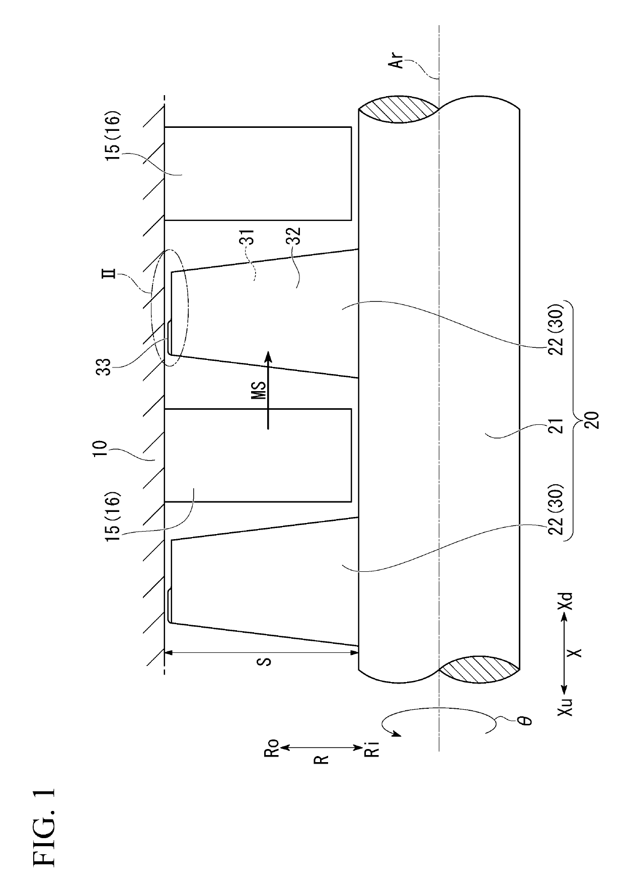
[0048]With reference to FIGS. 1 to 9, a first embodiment of the compressor will be described.
[0049]First, a compressor of the comparative example will be described before describing the compressor of the present embodiment.
[0050]The compressor of the comparative example is an axial compressor. As illustrated in FIG. 7, this compressor includes a rotor 20x that rotates about an axis Ar, a casing 10 that covers an outer circumferential side of the rotor 20x, and a plurality of stator vane rows 15. Here, a direction in which the axis Ar extends will be referred to as an axial direction X. One side in this axial direction X will be referred to as an axial upstream side Xu, and the other side in this axial direction X will be referred to as an axial downstream side Xd. In addition, a side toward the axis Ar in a radial direction R with respect to the axis Ar will be referred to as a radial inner side Ri, and a side opposite thereto will be referred to as a radial outer side Ro. In additi...
second embodiment
[0103]With reference to FIG. 13, a second embodiment of the compressor will be described.
[0104]The compressor of the present embodiment differs from the compressor of the first embodiment in only the blade. Thus, hereinafter, a blade 30a of the compressor of the present embodiment will be described in detail.
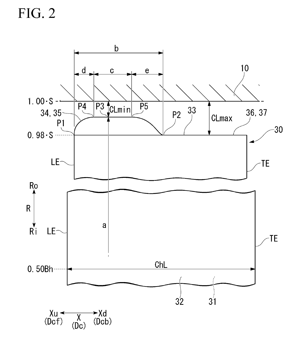
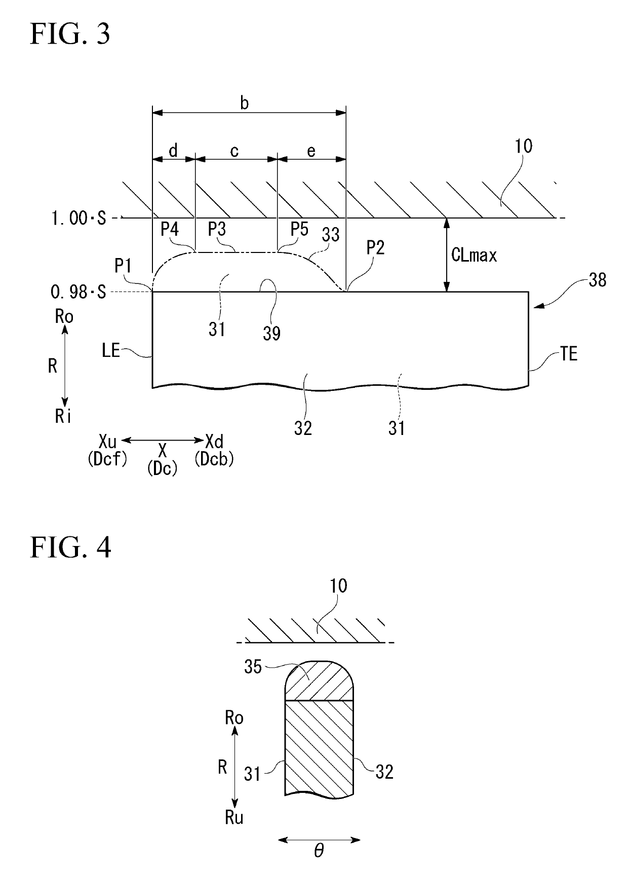
[0105]Similar to the blade 30 of the first embodiment, the blade 30a of the present embodiment also has the leading edge LE, the trailing edge TE, the positive pressure surface 31, the negative pressure surface 32, and a tip portion 33a.
[0106]Similar to the tip portion 33 of the first embodiment, the tip portion 33a of the present embodiment also has an upstream-side region 34a including the leading edge LE, and a downstream-side region 36a including the trailing edge TE. The upstream-side region 34a has a small clearance formation portion 35a. The downstream-side region 36a forms a large clearance formation portion 37a throughout the entire region of this downstream-side regio...
third embodiment
[0131]With reference to FIG. 15, a third embodiment of the compressor will be described.
[0132]The compressor of each of the foregoing embodiments is an axial compressor. On the other hand, a compressor of the present embodiment is a centrifugal compressor. The compressor of the present embodiment includes a rotor 20b that rotates about the axis Ar, and a casing 10b that covers the outer circumferential side of the rotor 20b. In the present embodiment, a direction in which the axis Ar extends will be referred to as the axial direction X. One side of this axial direction X will be referred to as the axial upstream side Xu, and the other side in this axial direction X will be referred to as the axial downstream side Xd. In addition, a side toward the axis Ar in the radial direction R with respect to the axis Ar will be referred to as the radial inner side Ri, and a side opposite thereto will be referred to as the radial outer side Ro. In addition, the circumferential direction with res...
PUM
 Abstract
Description
Claims
Application Information
 - R&D
- Intellectual Property
- Life Sciences
- Materials
- Tech Scout
- Unparalleled Data Quality
- Higher Quality Content
- 60% Fewer Hallucinations
Browse by: Latest US Patents, China's latest patents, Technical Efficacy Thesaurus, Application Domain, Technology Topic, Popular Technical Reports.
© 2025 PatSnap. All rights reserved.Legal|Privacy policy|Modern Slavery Act Transparency Statement|Sitemap|About US| Contact US: help@patsnap.com