Lockup device of hydraulic torque transmission device

a transmission device and lockup technology, applied in the direction of rotary clutches, fluid couplings, gearings, etc., can solve the problems of low response properties, low response properties, and prone to drag torque problems, so as to improve lockup response properties and reduce drag torque

Inactive Publication Date: 2008-04-22
EXEDY CORP
View PDF6 Cites 2 Cited by
  • Summary
  • Abstract
  • Description
  • Claims
  • Application Information

AI Technical Summary

Benefits of technology

[0013]An object of the present invention is to provide a lockup device having three friction surfaces, and particularly a lockup device that can improve lockup response properties, and can reduce a drag torque between a piston and a friction plate in the lockup OFF state.
[0017]In the lockup ON state and lockup OFF state described above, since the piston is unrotatably, axially, and elastically coupled to the drive member via the coupling member, a force acts to return the piston to an axial position where the elastic force of the coupling member is released, i.e., where the coupling member attains the free state. In the lockup ON operation, the pressure of the working fluid in the space on the front cover side of the piston is initially higher than the pressure of the working fluid in the space on the turbine side of the piston, and the piston is initially shifted axially toward the turbine. Therefore, it may be difficult to move rapidly and axially toward the front cover. Even in this state, the piston can be rapidly and axially moved toward the front cover by utilizing the elastic force of the coupling member. Further, in the lockup OFF operation, the pressure in the space on the turbine side of the piston is initially higher than the pressure in the space on the front cover side of the piston. Even in this state, the piston can be moved rapidly toward the turbine by utilizing the elastic force of the coupling member. Further, in the lockup OFF state, a clearance can be ensured between an intermediate plate and the pushing portion of the piston.
[0018]According to the lockup device, as described above, the piston can be moved axially and rapidly by utilizing the elastic force of the coupling member in the lockup ON / OFF operations so that the lockup response property can be improved. In the lockup OFF state, since a clearance is ensured between the second friction plate and the pushing portion of the piston, it is possible to reduce a drag torque between the friction plate and the piston in the lockup OFF state.
[0021]According to the lockup device of the hydraulic torque transmission device of the present invention, since the piston is unrotatably, axially and elastically coupled to the drive member through the coupling member, the piston can be axially and rapidly moved by utilizing the elastic force of the coupling member in the lockup ON / OFF operations so that the lockup response properties can be improved. Further, in the lockup OFF state, a clearance is ensured between the second friction plate and the pushing portion of the piston, this structure can reduce a drag torque between the friction plate and the piston in the lockup OFF state.

Problems solved by technology

In the above case, when an operation is performed to attain the lockup ON state, the piston cannot rapidly move axially toward the front cover, resulting in low response property problems.
This likewise results in low response property problems.
Further, in the conventional lockup device having the three friction surfaces, the second friction plate is axially movable so that a clearance cannot be ensured between a pushing portion of the piston and the second friction plate in the lockup OFF state.
Thus drag torque problems are liable to occur.

Method used


Image

  • Lockup device of hydraulic torque transmission device
  • Lockup device of hydraulic torque transmission device
  • Lockup device of hydraulic torque transmission device

Examples


Embodiment Construction

[0028]Selected embodiments of the present invention will now be explained with reference to the drawings. It will be apparent to those skilled in the art from this disclosure that the following descriptions of the embodiments of the present invention are provided for illustration only and not for the purpose of limiting the invention as defined by the appended claims and their equivalents.

[0029]An embodiment of a lockup device of a hydraulic torque transmission device according to the invention will now be described with reference to drawings.

(1) Overall Structure of a Torque Converter

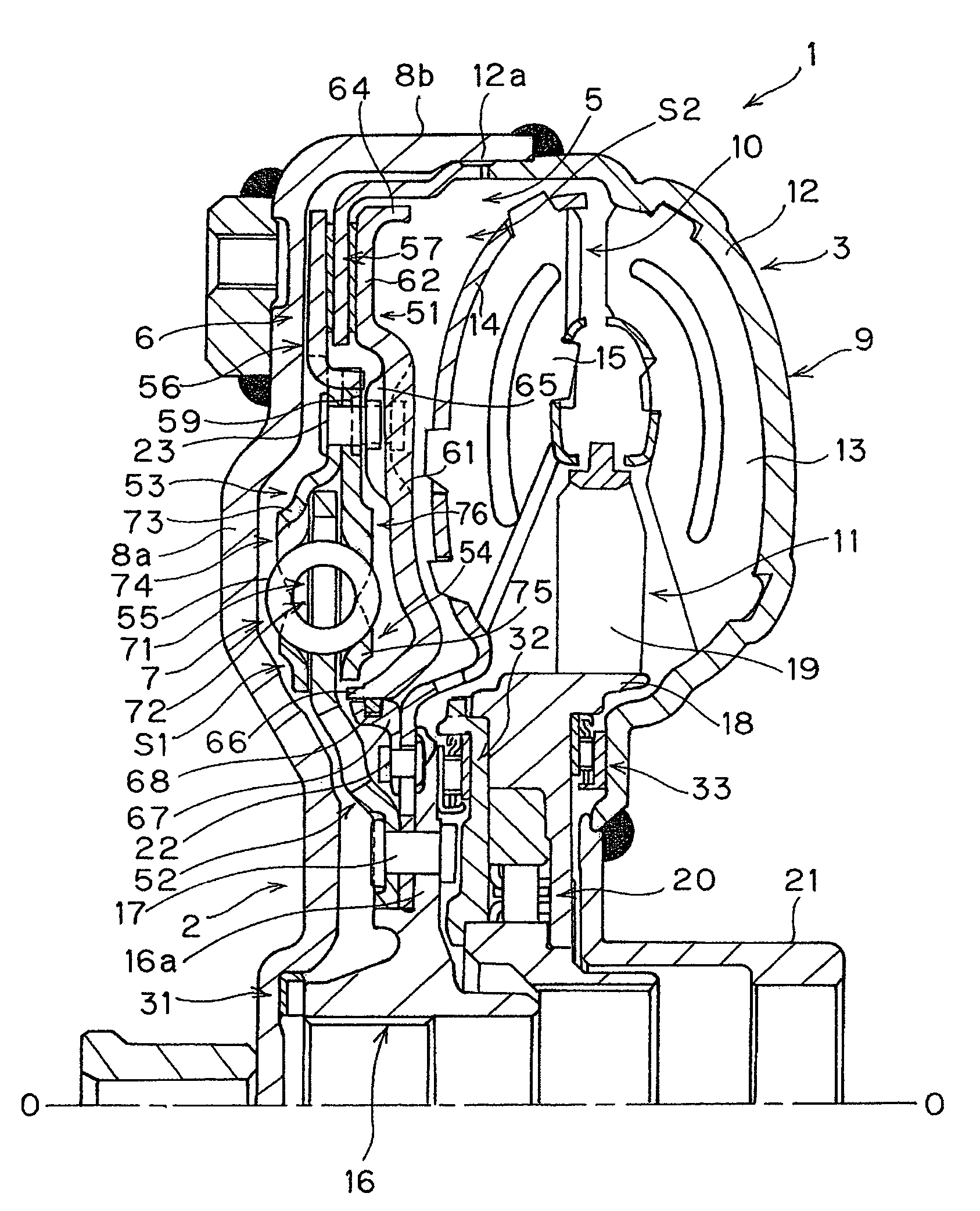
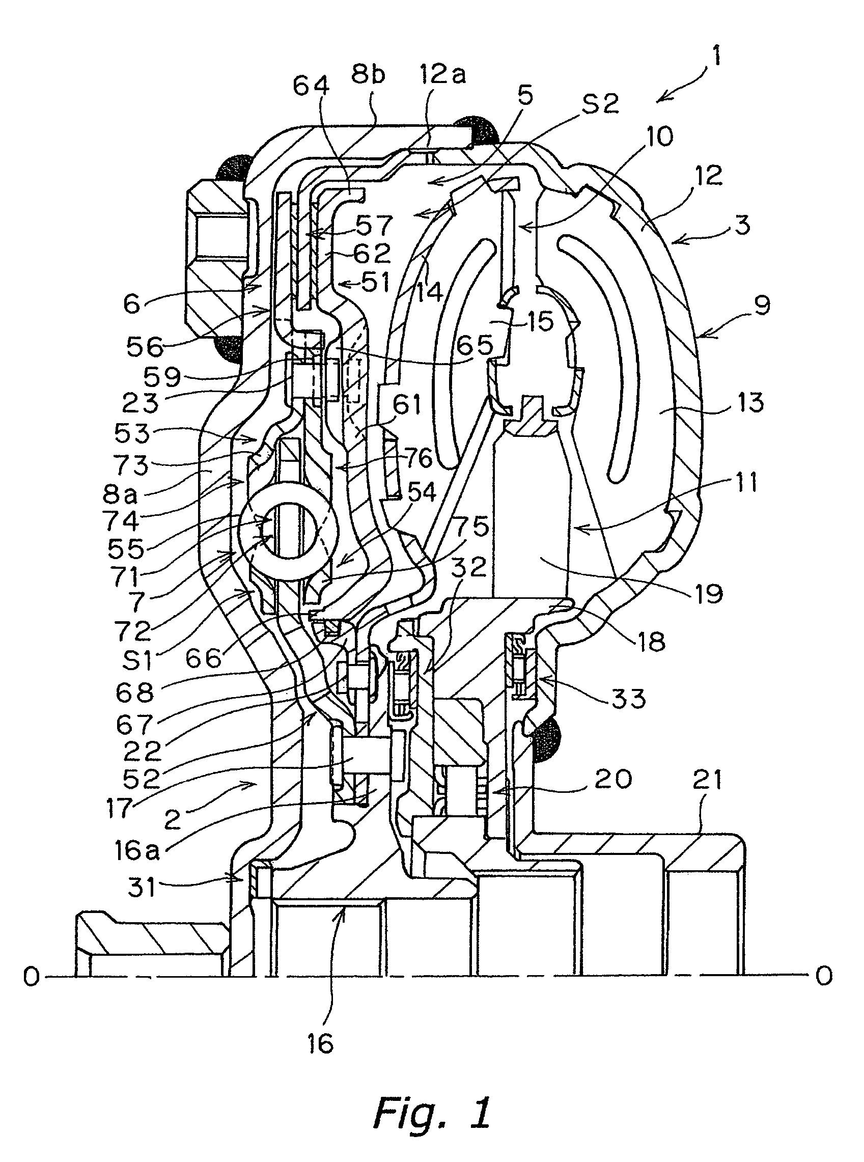
[0030]FIG. 1 is a schematic cross-sectional view of a torque converter 1 employing a device of the hydraulic torque transmission device according to a first preferred embodiment of the present invention. On the left side in FIG. 1, an engine (not shown) is arranged, and a transmission (not shown) is arranged on the right side. In FIG. 1, O-O indicates a rotation axis of the torque converter 1.

[0031]The...


PUM


Abstract

A lockup device 5 includes a damper mechanism 7, a plate 56, a plate 57, a piston 51, and a plate 59. The damper mechanism 7 has a plate 52 rotating together with the turbine 10, and plates 53 and 54 rotatable with respect to the plate 52. The plate 56 is unrotatable and axially movable with respect to the plates 53 and 54. The plate 57 is unrotatable and axially movable with respect to the front cover 2, and is arranged on the turbine side of the plate 52. The piston 51 is arranged on the turbine side of the plate 56, and is elastically and unrotatably coupled in an axial direction to the plates 53 and 54 through the plate 59.

Description

CROSS-REFERENCE TO RELATED APPLICATIONS[0001]This application claims priority to Japanese Patent Application Nos. 2004-312523 and 2004-330957. The entire disclosures of Japanese Patent Application Nos. 2004-312523 and 2004-330957 are hereby incorporated by reference.BACKGROUND OF THE INVENTION[0002]1. Field of the Invention[0003]The present invention relates to a lockup device of a hydraulic torque transmission device. Specifically, the present invention relates to a lockup device of a hydraulic torque transmission device including a front cover supplied with a torque, an impeller, which is fixed to the front cover to form a fluid chamber filled with working fluid, and a turbine opposed to the impeller. More specifically, the invention relates to the lockup device, which is arranged between the front cover and the turbine to couple mechanically the front cover and the turbine together.[0004]2. Background Information[0005]A torque converter is a kind of hydraulic torque transmission ...

Claims


Application Information

Patent Timeline
Patent Type & Authority Patents(United States)
IPC IPC(8): F16H45/02
CPCF16H45/02F16H2045/0284
Inventor TOMIYAMA, NAOKI
Owner EXEDY CORP
Why Eureka
Try Eureka