
Soldering iron tip

a soldering iron and tip technology, applied in the direction of metal-working equipment, soldering equipment, manufacturing tools, etc., can solve the problems of limited use, lack of mobility of soldering irons that must be plugged into a conventional electrical outlet, and current types of soldering irons, so as to reduce the risk of operator and/or his or her surroundings being burned, the effect of reducing the risk of the tip becoming stuck in the join

Active Publication Date: 2019-10-03
AXINTE DRAGOS
View PDF3 Cites 5 Cited by
  • Summary
  • Abstract
  • Description
  • Claims
  • Application Information

AI Technical Summary

Benefits of technology

The patent describes a new soldering iron design that has several technical benefits. Firstly, it eliminates the need for a separate switch because the electricity can only flow when the two tips are connected. Secondly, the alarmingly hot tip can quickly heat up and cool down, reducing the risk of burning the operator or the environment. Lastly, the material used for the tip prevents it from getting stuck in the joint, which means it can be used for a longer period of time. Additionally, the soldering iron also includes a light that can be controlled by a separate switch, allowing the operator to see in the dark without needing to heat the tip. This feature is particularly useful when working in places with no lighting.

Problems solved by technology

A number of problems exist with the current types of soldering irons.
Soldering irons that must be plugged into a conventional electrical outlet lack mobility and are restrictive in use.
If the soldering iron has not completely cooled down between uses, subsequent uses may not require as much startup time, but are still not immediate.
Similarly, the time required for desired cooling can be substantial, posing the danger of burns to the operator and his or her surroundings after the tool has been removed from the work surface and before the tool has cooled.
Furthermore, metal tips may become soldered to the connection, damaging the connection as the tip is removed and requiring further repair.
Existing cordless soldering irons resolve the mobility issues with soldering irons connected to conventional outlets, but at the cost of further problems.
Butane irons require the operator to store and maintain a highly flammable gas and do not resolve the other deficiencies noted above.
A disadvantage of this system is the inability to use the light without heating the tip of the soldering iron.
A visual inspection of the soldered connection may not always accurately determine whether or not the connection has been formed correctly and is now electrically conductive.

Method used


Image

  • Soldering iron tip
  • Soldering iron tip
  • Soldering iron tip

Examples


Embodiment Construction

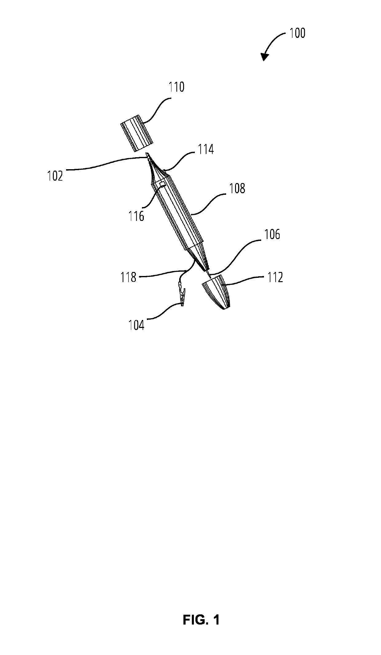
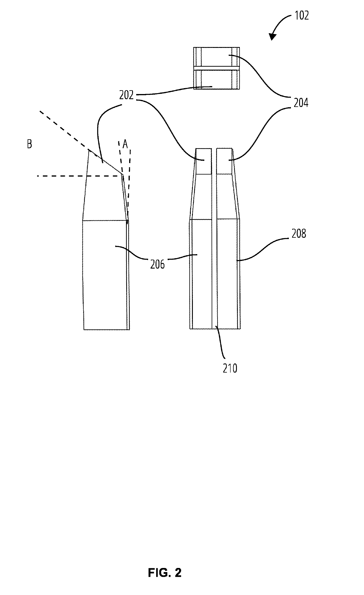
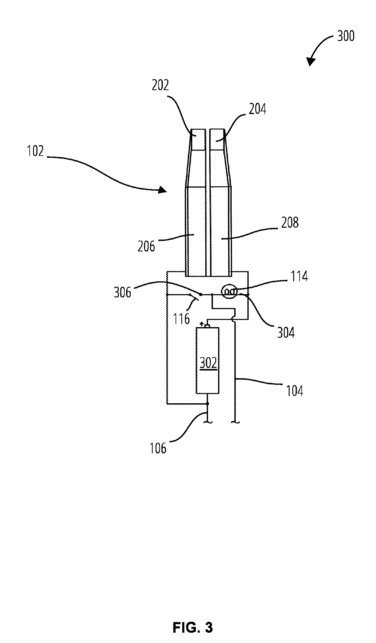
[0024]Referencing FIG. 1 throughFIG. 3, one embodiment of a soldering iron 100 formed in accordance with the present invention is shown. The soldering iron 100 includes a soldering tip 102 attached to a body 108, a light 114 disposed on the body 108 to illuminate the soldering tip 102 and surrounding work surfaces (not shown), a switch 116 disposed on the body 108 to control the light 114, a lead 104 and a continuity testing probe 106 disposed on body 108. Cover 110 and cover 112 are available to protect the soldering tip 102 and probe 106 / lead 104 from damage. The covers are removably fixed to the body 108 by conventional means, for example, a friction fit, a clamp, threaded surfaces, etc.

[0025]In more detail, the body 108 includes an elongate substantially tubular member of rigid heat resistant material, such as plastic or other materials known to those skilled in the art. The body 108 is a unitary structure, assembled in parts, and configured to hold the sub-components described ...


PUM


Abstract

The present invention provides a soldering iron with a tip having two separate halves that are electrically isolated from one another. When both halves of the tip are applied to an electrically conductive material, such as the material to be soldered, an electrical circuit between the tip halves and an electrical power source is completed. Therefore, the tip can reach operating temperatures quickly. When the tip is removed from the joint, the electrical circuit is broken and the tip material may quickly cool to a temperature safe for human contact. The tip material permits higher power outputs than other battery operated portable soldering irons and heat and cools faster the conventional soldering tips.

Description

FIELD[0001]The present invention relates to cordless electrical devices, more specifically, to soldering irons and soldering iron tips.BACKGROUND[0002]In many industries and for some hobbyists, it is necessary to manually make electrically conductive connections between various electrical components. In order to make such connections, a wide variety of soldering irons have been developed, for use in a variety of applications, ranging from repair of printed circuit boards, use in the telecommunications industry, and use in the manufacture and repair of heavy industrial electrical and electro-mechanical equipment. Existing soldering irons vary by power source, application, performance, shape, size, temperature, tip type, heat source, price, and portability.[0003]Regardless of the size or capability of the soldering iron, existing soldering iron tips are generally categorized into two main types. The first consists of a heating element surrounded by a non-conductive film material, whic...

Claims


Application Information

Patent Timeline
IPC IPC(8): B23K3/03B23K3/02
CPCB23K3/0315B23K3/0323B23K3/0307B23K3/025
Inventor AXINTE, DRAGOS
Owner AXINTE DRAGOS
Learn More