
Torque detection unit and vehicle

a technology for torque detection and detection units, applied in the direction of work measurement, measurement devices, instruments, etc., can solve the problems of misinterpretation of the evaluation of the detected value, the process is subject to the corresponding measurement error, etc., and achieve the effect of high reliability and accuracy

Active Publication Date: 2019-09-26
ROBERT BOSCH GMBH
View PDF0 Cites 3 Cited by
  • Summary
  • Abstract
  • Description
  • Claims
  • Application Information

AI Technical Summary

Benefits of technology

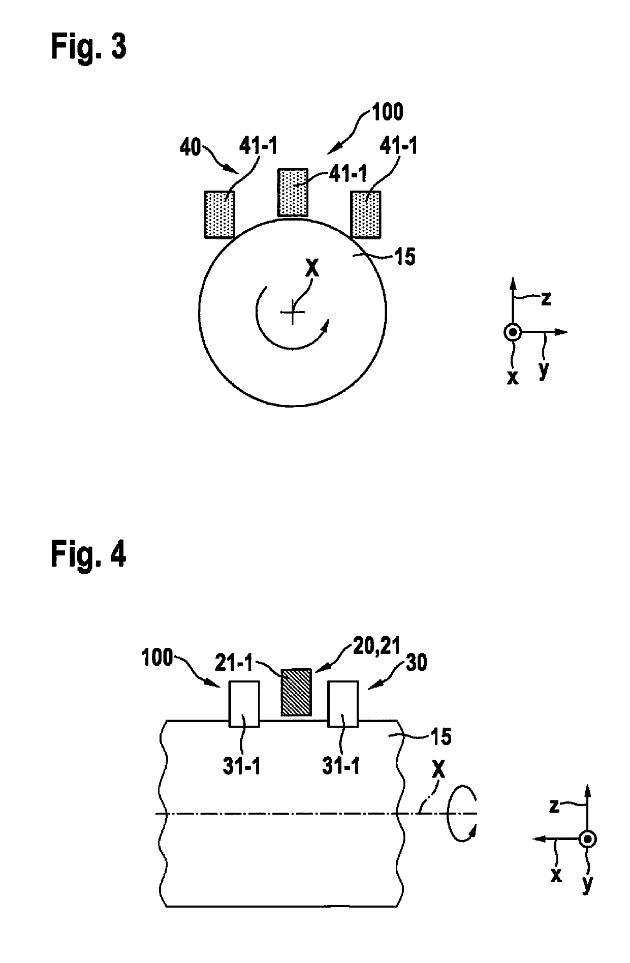
The present invention relates to a torque detection unit for determining torque on a rotating shaft, such as a crankshaft, of a vehicle. The unit uses a magnetic field and sensors to detect changes in the magnetic field caused by the torque. The sensors have different orientations with respect to the shaft, which allows for accurate and reliable detection of torque without needing special material provisions on the shaft. The sensors are connected in a bridge circuit, which improves accuracy and reproducibility. The sensor unit is designed to have high sensitivity and accuracy with respect to the shaft and its rotational axis. The torque detection unit is compact and easy to install.

Problems solved by technology

The drawback is that, on the one hand, only the electrical or magnetic variables are resorted to, which the material itself to which the torque is applied provides.
On the other hand, such a procedure is subject to corresponding measuring errors due to perturbations in the thermal area, for example in terms of a temperature drift, or in the mechanical area, e.g., in terms of occurring vibrations or deformations of the drive components.
These measuring errors often remain undetected and may result in misinterpretations in the evaluation of the detected values of the presumably occurring torque.

Method used


Image

  • Torque detection unit and vehicle
  • Torque detection unit and vehicle
  • Torque detection unit and vehicle

Examples


Embodiment Construction

[0039]With reference to FIGS. 1 through 26, exemplary embodiments of the present invention are described hereafter in greater detail. Identical and equivalent as well as identically or equivalently acting elements and components are denoted by the same reference numerals. The detailed description of the denoted elements and components is not provided each time they occur.

[0040]The shown features and further properties may be arbitrarily separated from one another and arbitrarily combined with one another, without departing from the core of the present invention.

[0041]Initially, with reference to FIG. 26, an electric bicycle is described in detail by way of example as a preferred specific embodiment of vehicle 1 according to the present invention.

[0042]Being an electric bicycle, vehicle 1 includes a frame 12 on which a front wheel 9-1, a rear wheel 9-2 and a crank mechanism 2 including two cranks 7, 8 having pedals 7-1 and 8-1 are situated. An electric drive 3 is integrated into cran...


PUM


Abstract

The invention relates to a torque detection unit (100) for actively detecting a torque acting on a shaft (15), and in particular on a crankshaft (15), of a vehicle (1) drivable by muscle power and / or by motor power along a rotational axis (X), including an excitation unit (20), which is designed to apply a magnetic field which changes over time to the shaft (15), and a first sensor unit (30) and a second sensor unit (40), which are designed to detect a magnetic field carried by the shaft (15), the first and the second sensor unit (40), in particular with an otherwise identical setup, having different orientations with respect to one another so that they, during operation, are oriented differently from one another with respect to the shaft (15), and in particular with respect to the rotational axis (X).

Description

BACKGROUND INFORMATION[0001]The present invention relates to a torque detection unit and to a vehicle. The present invention relates in particular to a torque detection unit for actively detecting a torque acting on a shaft, and in particular on a crankshaft, of a vehicle drivable by muscle power and / or by motor power along a rotational axis, and to a vehicle, a bicycle, an electric bicycle, an e-bike, a pedelec or the like drivable by muscle power and / or by motor power.[0002]During the monitoring and / or control of drive units, for example in the area of vehicle engineering, it is often desirable to detect the torque acting on a shaft of a drive unit.[0003]Conventionally, torque detection units are used for this purpose, which utilize effects related to the mechanical stresses in the shaft to be able to infer the value of a torque acting on the axle. Materials may be used here which show a piezoelectric effect dependent on the mechanical stresses or an inverse magnetostrictive effec...

Claims


Application Information

Patent Timeline
IPC IPC(8): G01L3/10
CPCG01L3/105
Inventor DOELLING, ROLANDO
Owner ROBERT BOSCH GMBH
Learn More