Power transmission structure of hybrid vehicle with one motor generator and three clutches

a technology of hybrid vehicles and transmission structures, which is applied in mechanical equipment, transportation and packaging, and manufacturing, etc., can solve the problems of increasing fabrication costs, increasing fuel consumption, and complicated engine room design, so as to improve the fuel efficiency of the engine, prevent the effect of output power reduction, and large capacity

Inactive Publication Date: 2019-09-26
KANG MYUNGKOO +3
View PDF7 Cites 1 Cited by
  • Summary
  • Abstract
  • Description
  • Claims
  • Application Information

AI Technical Summary

Benefits of technology

[0016]Accordingly, the present invention has been made keeping in mind the above problems occurring in the related art, and the present invention is intended to propose a power transmission structure of a hybrid vehicle having a simple configuration, able to significantly reduce fabrication costs and maintenance costs, and having superior fuel efficiency and performance as well as a superior operating mechanism.
[0025]According to the present invention, output power can be prevented from being reduced by the driven rotation of the motor, in which the engine and the motor are connected to the output shaft, whereby the motor having a large capacity in comparison to the displacement of the engine can be mounted. It is therefore possible to improve the fuel efficiency of the engine and significantly increase the amount of power generated by the motor. In addition, according to the present invention, mechanical power and electricity can be generated by a single motor, which also functions as a starter. This configuration can significantly reduce electronic control units, thereby causing fabrication to be simple. Since a single high-voltage electrical circuit and a single high-voltage power control unit (PCU) are used, it is possible to minimize the occurrence of interferences due to the complicated electrical circuit configuration of the related art. It is therefore possible to reduce the fabrication costs of a vehicle and facilitate the maintenance and repair of the control units.
[0026]Furthermore, according to the present invention, the three clutches operating independently of each other are provided. This configuration allows the motor to propel the vehicle and enables regenerative electric power generation by the motor and electric power generation by the engine. It is therefore possible to improve fuel efficiency and maximize the efficiency of electric power generation and regeneration.
[0027]In addition, according to the present invention, a motor having a suitable capacity in comparison to the displacement of the engine can be selected. Furthermore, power input from the engine can be suitably adjusted to the optimum number of revolutions of the motor. It is therefore possible to propel the vehicle with optimum fuel efficiency and optimize the efficiency of power generation by the motor.

Problems solved by technology

However, in this case, two electrical connector units and two control units must be separately disposed, thereby increasing fabrication costs, which is problematic.
This causes the design of the engine room to be complicated.
In addition, electrical interferences may occur between the electrical connector units, between the control units, and between the electrical connector units and the control units, thereby frequently causing malfunctions.
Among these driving modes, the series mode has the worst fuel efficiency in high-speed driving with high rpm.
Thus, the operation in series mode must be restricted as much as possible during high-speed driving with high rpm since this mode lacks the fuel efficiency to enable a vehicle to be called “hybrid.” In addition, it is required to improve the efficiency of electric power generation by the engine and the efficiency of regenerative electric power generation in order to improve the fuel efficiency of a hybrid vehicle in the series mode.
In this case, rotatory power generated by the engine may be reduced due to the driven rotation of the motor shaft (parasitic energy consumption of the motor generator).
Then, a motor having a large capacity cannot be mounted.
Thus, hybrid vehicles from Nissan have limited ability to improve the efficiency of electric power generation by the engine and the efficiency of regenerative electric power generation since only a small motor in comparison to the displacement of the engine can be mounted.
However, the former approach does not have the clutch between the transmission and the motor even in the case in which the transmission is assumed to be the CVT that cannot have a neutral position.
In this configuration, it is impossible to generate power by rotating the driving motor using the engine.
Therefore, this approach has the same problems as the above-described Sonata hybrid vehicle from Hyundai.
The latter approach has the same problems since one clutch of the double clutch (substantially a dual clutch regardless of the name “double clutch”) remains connected to the transmission.
Thus, this approach also has the same problems as the above-described hybrid vehicle from Nissan.

Method used


Image

  • Power transmission structure of hybrid vehicle with one motor generator and three clutches
  • Power transmission structure of hybrid vehicle with one motor generator and three clutches
  • Power transmission structure of hybrid vehicle with one motor generator and three clutches

Examples


Embodiment Construction

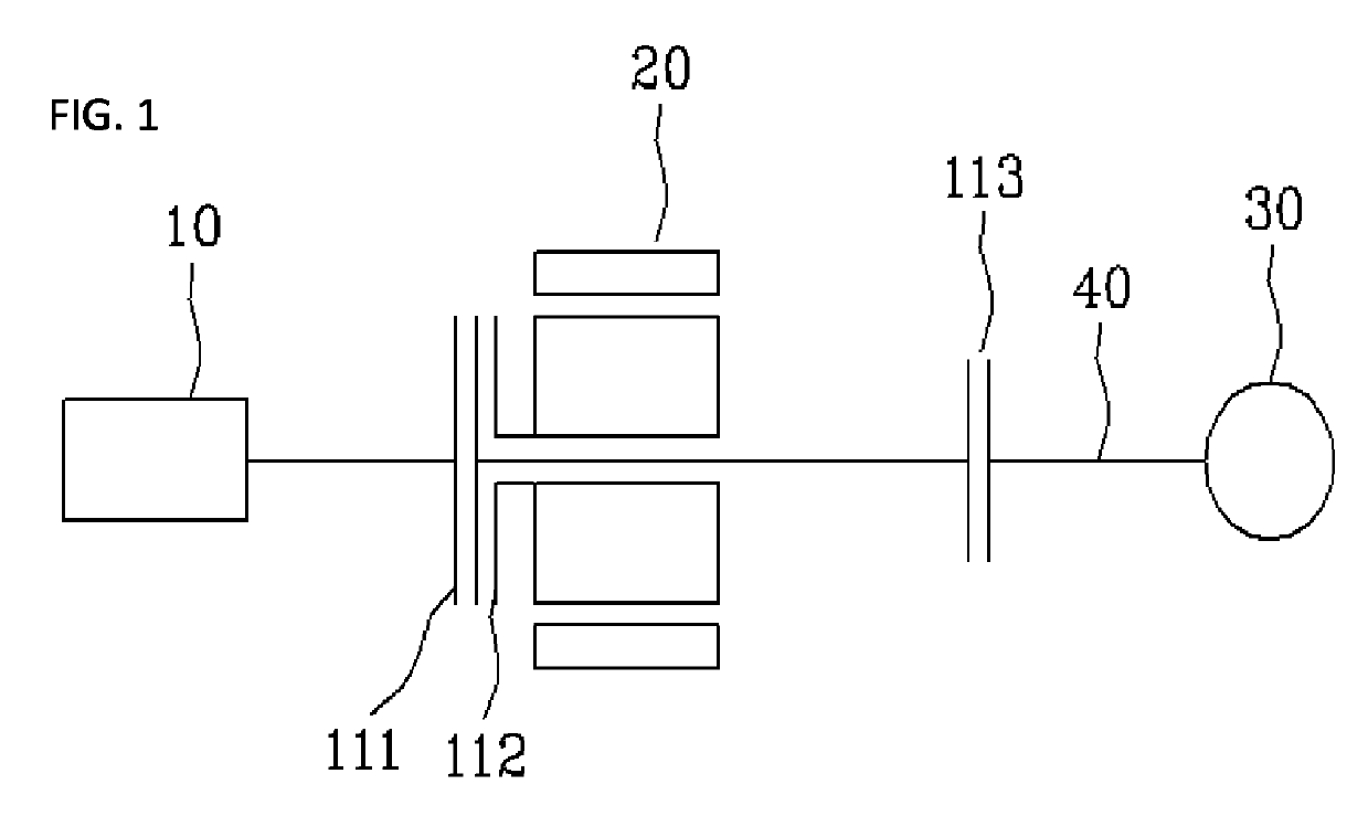
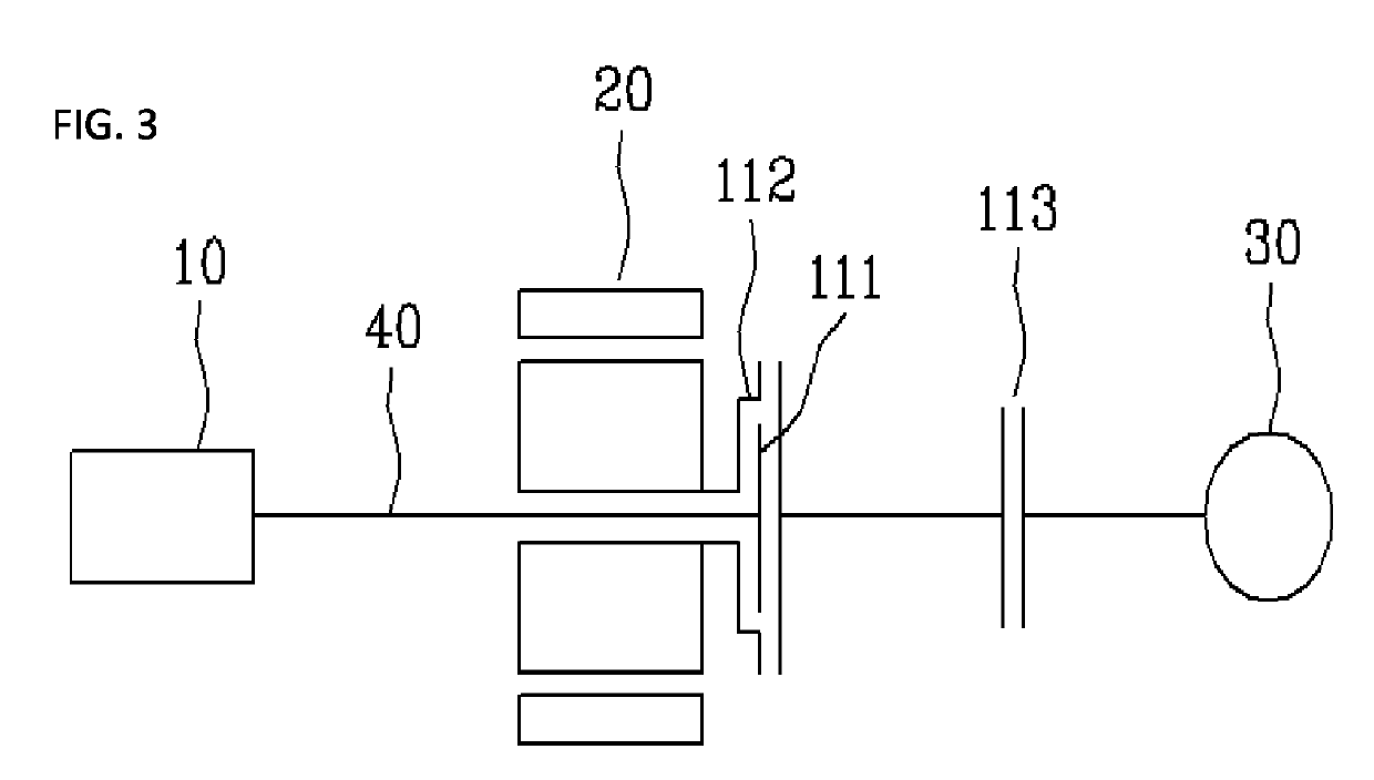
[0043]Reference will now be made in greater detail to exemplary embodiments of the present invention, examples of which are illustrated in the accompanying drawings. Wherever possible, the same reference numerals will be used throughout the drawings and the description to refer to the same or like parts. In the following description of the embodiments of the present invention, descriptions of components not directly related to the principle of the present invention or components obvious to a person skilled in the art will be omitted.

[0044]FIGS. 1 to 8 are schematic configuration views illustrating exemplary power transmission structures of hybrid vehicles according to the present invention. As illustrated in FIGS. 1 to 8, according to the technical features of the present invention, an engine 10, a motor 20, a transmission 30, and first to third clutches 111, 112, and 113 or a triple clutch 211, 212, and 213 are provided. Detailed descriptions of these configurations will be now giv...


PUM


Abstract

A power transmission structure of a hybrid vehicle includes a motor generator, a first clutch, a second clutch, a third clutch, an engine, a motor, and an output shaft transferring power generated by the engine and power generated by the motor to a transmission. The motor is disposed parallel to the engine, the output shaft extends through a central portion of the motor and is connected to the transmission. The first clutch and the second clutch are disposed as a double clutch on the output shaft between the engine and the motor. The third clutch is disposed between the motor and the transmission to enable and disable power to be transferred via the output shaft.

Description

CROSS REFERENCE TO RELATED APPLICATIONS[0001]This application is a divisional application of U.S. patent application Ser. No. 14 / 964,897, filed on Dec. 10, 2015 (currently pending), the disclosure of which is herein incorporated by reference in its entirety. The U.S. patent application Ser. No. 14 / 964,897 claims priority to Korean Application No. 10-2015-0040940 filed on Mar. 24, 2015, the entire contents of which are incorporated herein by reference.BACKGROUND OF THE INVENTIONField of the Invention[0002]The present invention generally relates to a power transmission structure in a hybrid vehicle. More particularly, the present invention relates to a power transmission structure of a hybrid vehicle, in which three clutches regulating output power from each of an engine, a driving motor, and a transmission are provided independently of each other, whereby the driving motor can be prevented from acting as a load in the process of transferring power generated by the engine to the trans...

Claims


Application Information

Patent Timeline
Patent Type & Authority Applications(United States)
IPC IPC(8): B60K6/387B60K6/48F16H3/00
CPCY02T10/6234Y10S903/914B60K6/442Y02T10/6221F16H3/006B60Y2200/92Y10S903/915B60K6/48B60K6/387Y02T10/62
Inventor KANG, MYUNGKOOJEON, HYOJEONGKANG, SEUNGMOKANG, SUEJEONG
Owner KANG MYUNGKOO
Why Eureka
Try Eureka