
Footwear sole

a sole and shoe technology, applied in the field of footwear soles, can solve the problems of increasingaffecting the comfort of wear and tear, and affecting the comfort of wear and tear, and achieve the effects of reducing the volume and weight of footwear

Active Publication Date: 2019-09-26
WOLVERINE OUTDOORS
View PDF0 Cites 18 Cited by
  • Summary
  • Abstract
  • Description
  • Claims
  • Application Information

AI Technical Summary

Benefits of technology

This patent describes a shoe that can both absorb shock and provide energy return. It is made up of multiple waves that have alternating crests and troughs. The crests make contact with the ground to provide stability, while the troughs help to absorb force. The ratio between the widths of the crests and troughs can be adjusted to optimize performance. The shoe is flexible and stable, while still providing exceptional cushioning and energy return.

Problems solved by technology

While this does provide cushioning and shock attenuation, it also can increase the volume and weight of the footwear significantly.
Further, due to the soft material, the sole can tend to roll laterally and medially in some cases, which can render the footwear unstable on certain ground surfaces or for certain activities.
Additionally, the soft material of the sole can degrade over time, decreasing its energy return.
Lastly, where the soft material of the sole is marginally protected from the elements and abrasion, or where the soft material engages the ground, that material can wear quickly, decreasing the longevity of the footwear.
While these constructions can address prior issues, they also can present new issues.
For example, air bladders can be punctured or can crack where materials flex over time.
Thus, the bladders can leak, reducing their shock attenuation and rebounding capabilities.
Shock pods can sometimes add additional weight to a sole unit, which can hinder its performance.
Shock pods also can require extra manufacturing and assembly costs, as well as added complexity to integrate the pods into the footwear.

Method used


Image

  • Footwear sole
  • Footwear sole
  • Footwear sole

Examples


Embodiment Construction

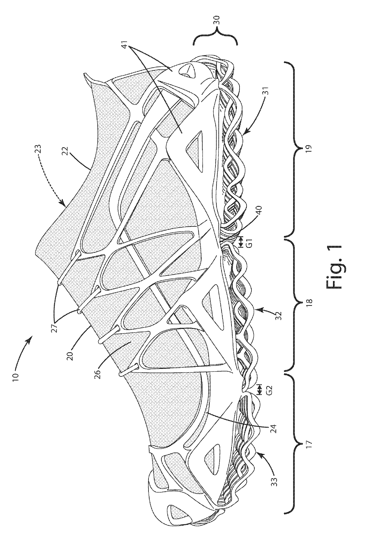
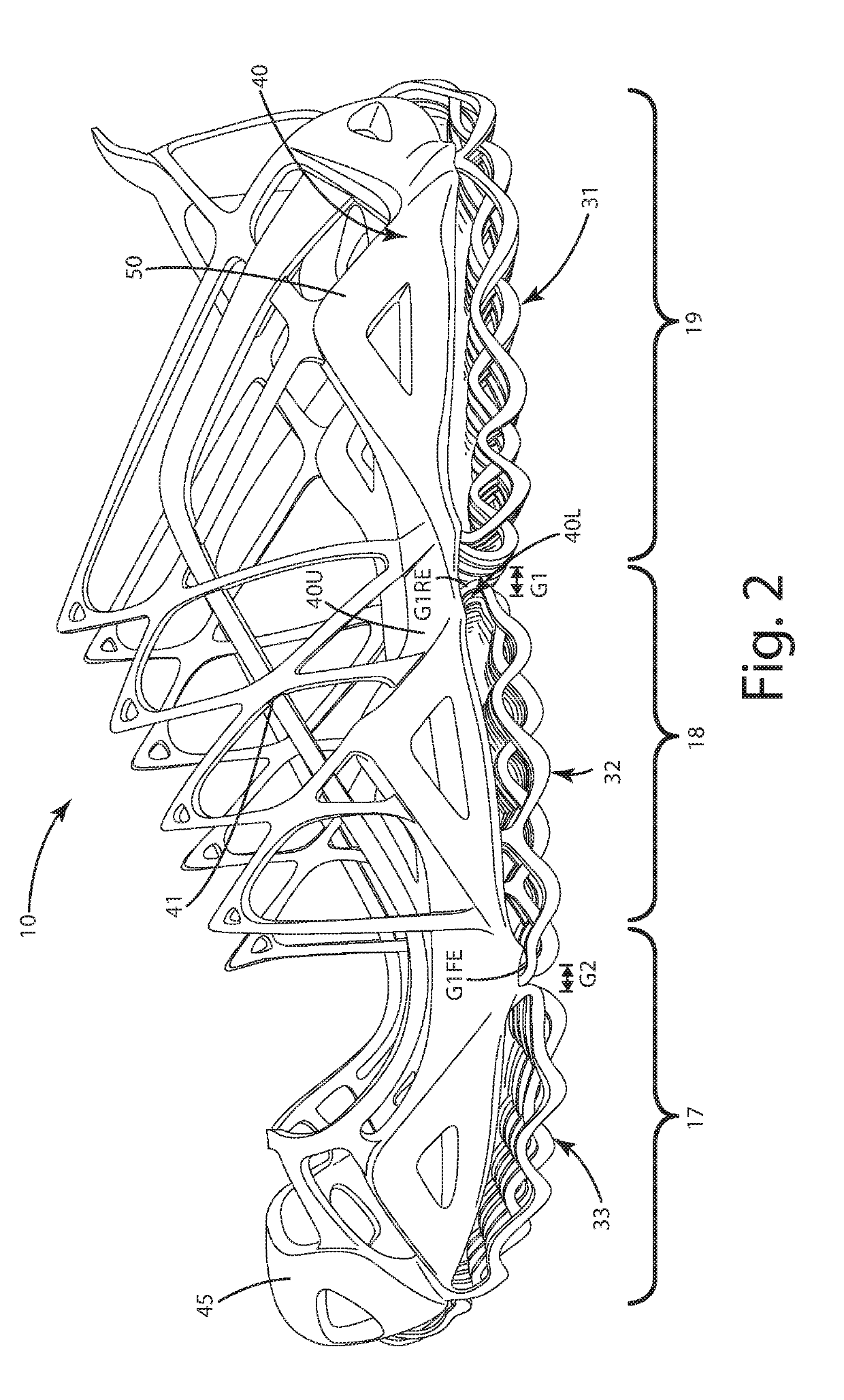
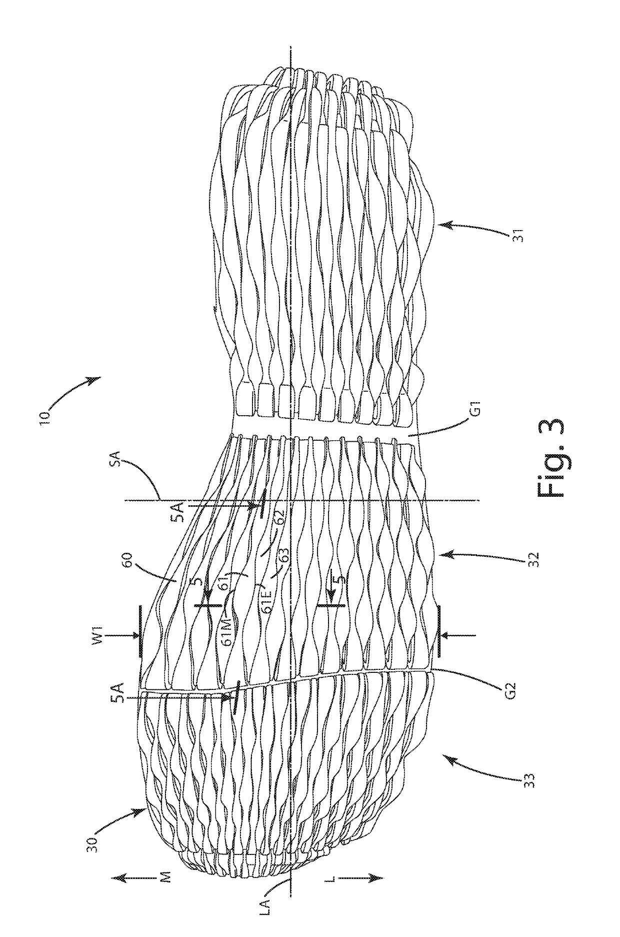
[0025]Footwear constructed in accordance with a current embodiment is shown in FIGS. 1-7 and generally designated 10. Generally, the footwear 10 includes an upper 20 and a sole 30 joined with the upper. The sole 30 can include a longitudinal axis LA and a width W1, the width W1 spanning from a lateral side L to a medial side M across the longitudinal axis LA. The sole 30 can include a base 40 to which a support cage 50 is joined. The support cage 20 can extend upwardly along an exterior surface 22 of the upper. The sole 30 can include one or more sections comprising a plurality of wave elements 60. For example, the sole 30 can include a heel section 31, an arch or midfoot section 32 and a forefoot section 33. The wave elements 60 can include exemplary first wave element 61, second wave element 62 and third wave element 63. The wave elements can each include a plurality of respective crests and troughs, given the wave form shape of the wave elements 60.

[0026]Certain ones of the wave ...


PUM


Abstract

A footwear having a shock attenuating and cushioning sole is provided, including a base to which first and second wave elements are joined, each element including alternating crests and troughs. The crests are wide and can each form a ground contact surface, whereas the troughs can be narrower than the crests. Crests of one element are disposed adjacent the troughs of another element. The widths of the crests to those of the troughs can be in at least a 2:1 ratio. Forward and rearward ends of the elements are connected to the base, and the troughs intermittently join with the base to secure the elements between the ends and to impair lateral movement. Different groups of wave elements can be grouped together to form a forefoot section, a heel section and / or an arch section, with the sections separated from and compressible independent of the other sections.

Description

BACKGROUND[0001]The present invention relates to footwear and, more particularly, to a footwear sole having exceptional shock attenuation, flexibility and energy return.[0002]Footwear manufacturers strive to produce footwear having exceptional cushioning capabilities and shock attenuation, particularly in the design of athletic, walking and work footwear, where increased cushion and energy return are primary objectives, balanced with stability. Typically, such footwear include a specialized sole having extensive padding and / or a very thick sole. Such a sole is usually constructed from soft and / or compliant materials to provide cushioning and dampening characteristics. While this does provide cushioning and shock attenuation, it also can increase the volume and weight of the footwear significantly. Further, due to the soft material, the sole can tend to roll laterally and medially in some cases, which can render the footwear unstable on certain ground surfaces or for certain activiti...

Claims


Application Information

Patent Timeline
IPC IPC(8): A43B13/18
CPCA43B13/04A43B13/28A43B13/183A43B3/0052A43B3/0057A43B13/122A43B13/125A43B13/141A43B13/185B29D35/02B33Y80/00
Inventor LOVEDER, CHRISTOPHER J.
Owner WOLVERINE OUTDOORS
Learn More