Crimp terminal

a technology of crimping terminals and terminals, which is applied in the direction of connection insulation, connection contact member materials, coupling device connections, etc., can solve the problems of aluminum core wires made of aluminum which are a base metal, and achieve the effect of reducing manufacturing difficulty

Active Publication Date: 2019-09-12
YAZAKI CORP
View PDF13 Cites 1 Cited by
  • Summary
  • Abstract
  • Description
  • Claims
  • Application Information

AI Technical Summary

Benefits of technology

[0018]According to the present invention, the crimp terminal that can reduce a difficulty of manufacturing while ensuring waterproof property with respect to the contact portion with the aluminum core wire, can be provided.

Problems solved by technology

If moisture adheres to such contact portion, the aluminum core wire made of aluminum which is a base metal could be corroded due to so-called dissimilar metal corrosion.

Method used


Image

  • Crimp terminal
  • Crimp terminal
  • Crimp terminal

Examples


first embodiment

[0069]In the following, an embodiment of the present invention will be explained variously. Firstly, a first embodiment will be explained along with modified examples thereof.

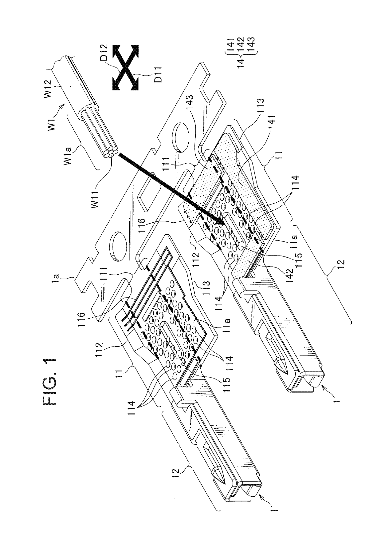
[0070]FIG. 1 illustrates a crimp terminal according to the first embodiment of the present invention.

[0071]A crimp terminal 1 according to this embodiment is configured to be crimped to an end portion W1a of a covered electric wire W1 having an aluminum core wire W11, at which the aluminum core wire W11 is exposed. The crimp terminal 1 includes a barrel portion 11, a terminal portion 12 and a seal member 14. In FIG. 1, two crimp terminals 1 are shown, of which one crimp terminal 1 is shown with the seal member 14 removed for the purpose of providing a view of shape of an inner surface of the barrel portion 11.

[0072]The barrel portion 11 and the terminal portion 12 are produced from a metal plate made of a copper alloy or the like using punching and sheet-metal processing, and a surface thereof is tin-plated or ...

second embodiment

[0149]FIG. 29 illustrates a crimp terminal according to the present invention. FIG. 30 illustrates how a seal member shown in FIG. 29 is attached to an inner surface of a barrel portion. In FIGS. 29 and 30, elements similar to those shown in FIGS. 1-8 are denoted by the same reference signs as FIGS. 1-8, and explanation of these similar elements is omitted in the following description. In FIG. 29, two crimp terminals 5 are shown, of which one crimp terminal 5 is shown with a seal member 14 removed for the purpose of providing a view of shape of an inner surface of a barrel portion 51.

[0150]In the crimp terminal 5 of this embodiment, a plurality of recesses 514 is dispersedly provided on an inner surface 51a of the barrel portion 51 over an entire region including a first region 51a-1, a second region 51a-2 and a third region 51a-3. A protrusion 515 is formed on the inner surface 51a at a location where the aluminum core wire W11 is to be placed, and is formed by pressing applied fro...


PUM


Abstract

Difficulty of manufacturing is reduced while ensuring waterproof property with respect to a contact portion with an aluminum core wire. A barrel portion of a crimp terminal includes an inner barrel piece and an outer barrel piece, and includes a seal member which is attached over a first region, a second region and a third region and which seals, after crimping, a space between the inner barrel piece and the outer barrel piece, an opening of the barrel portion on a terminal portion side, and a space between a covered portion and the barrel portion. An inner surface of the barrel portion is provided with a plurality of recesses arranged dispersedly, the recess having a circular shape in a plane view with respect to the inner surface.

Description

TECHNICAL FIELD[0001]The present invention relates to a crimp terminal configured to be crimp-connected to a covered electric wire having an aluminum core wire.BACKGROUND ART[0002]In recent years, a covered electric wire having an aluminum core wire has been used for a wire harness in place of a covered electric wire having a copper core wire. Some crimp terminals such as connector terminals, for example, are made of a copper alloy or the like and having a surface that is tin-plated or gold-plated. When the crimp terminal of this type is crimped to an end portion of the covered electric wire where the aluminum core wire is exposed, contact between dissimilar metals occurs between the aluminum core wire and a crimping barrel portion of the crimp terminal. If moisture adheres to such contact portion, the aluminum core wire made of aluminum which is a base metal could be corroded due to so-called dissimilar metal corrosion.[0003]Therefore, there has been proposed a crimp terminal havin...

Claims


Application Information

Patent Timeline
Patent Type & Authority Applications(United States)
IPC IPC(8): H01R4/18H01R4/62H01R4/70H01R43/048
CPCH01R4/62H01R4/185H01R4/70H01R43/048H01R4/188H01R13/5216H01R4/18
Inventor SATO, KEITAKAHASHI, KAZUHIDE
Owner YAZAKI CORP
Why Eureka
Try Eureka